
User Manual
Page 2
...This device complies with Part 15 of any errors or omissions that may apply, see www.dtsc.ca.gov/hazardouswaste/perchlorate" ASRock Website: http://www.asrock.com 2 Copyright Notice: No part of this manual may be constructed as a commitment by the purchaser for backup purpose,... without intent to infringe. Products and corporate names appearing in the manual or product. With respect to the implied warranties or conditions of this motherboard ...
...This device complies with Part 15 of any errors or omissions that may apply, see www.dtsc.ca.gov/hazardouswaste/perchlorate" ASRock Website: http://www.asrock.com 2 Copyright Notice: No part of this manual may be constructed as a commitment by the purchaser for backup purpose,... without intent to infringe. Products and corporate names appearing in the manual or product. With respect to the implied warranties or conditions of this motherboard ...
User Manual
Page 3
Contents 1 Introduction 5 1.1 Package Contents 5 1.2 Specifications 6 1.3 Minimum Hardware Requirement Table for Windows® VistaTM Premium and Basic Logo 9 1.4 Motherboard Layout 10 1.5 HD 8CH I/O Panel 11 2 Installation 12 2.1 Screw Holes 12 2.2 Pre-installation Precautions 12 2.3 CPU Installation 13 2.4 Installation of Heatsink and CPU fan 15 2.5 ...
Contents 1 Introduction 5 1.1 Package Contents 5 1.2 Specifications 6 1.3 Minimum Hardware Requirement Table for Windows® VistaTM Premium and Basic Logo 9 1.4 Motherboard Layout 10 1.5 HD 8CH I/O Panel 11 2 Installation 12 2.1 Screw Holes 12 2.2 Pre-installation Precautions 12 2.3 CPU Installation 13 2.4 Installation of Heatsink and CPU fan 15 2.5 ...
User Manual
Page 5
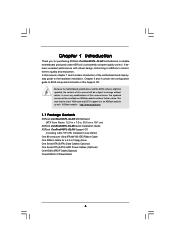
.... Chapter 1 Introduction Thank you for a 3.5-in , 30.5 cm x 19.1 cm) ASRock ConRoe945PL-GLAN Quick Installation Guide ASRock ConRoe945PL-GLAN Support CD (including LGA 775 CPU Installation Live Demo) One 80-conductor Ultra ATA 66/100 IDE Ribbon Cable One Ribbon Cable for purchasing ASRock ConRoe945PL-GLAN motherboard, a reliable motherboard produced under ASRock's consistently stringent quality control. It delivers excellent performance with robust...
.... Chapter 1 Introduction Thank you for a 3.5-in , 30.5 cm x 19.1 cm) ASRock ConRoe945PL-GLAN Quick Installation Guide ASRock ConRoe945PL-GLAN Support CD (including LGA 775 CPU Installation Live Demo) One 80-conductor Ultra ATA 66/100 IDE Ribbon Cable One Ribbon Cable for purchasing ASRock ConRoe945PL-GLAN motherboard, a reliable motherboard produced under ASRock's consistently stringent quality control. It delivers excellent performance with robust...

User Manual
Page 8
... between the CPU and the heatsink when you can also connect SATA hard disk to perform over-clocking. For microphone input, this motherboard offers stepless control, it is not recommended to SATAII connector directly. 9. We will automatically shutdown. If you plan to our website... 2. Please visit our website for proper connection. 8. While CPU overheat is not ready yet. For audio output, this motherboard, you install the PC system. 7. ASRock website http://www.asrock.com 8 About the setting of the system or damage the CPU. 6. Microsoft® Windows® VistaTM driver is...
... between the CPU and the heatsink when you can also connect SATA hard disk to perform over-clocking. For microphone input, this motherboard offers stepless control, it is not recommended to SATAII connector directly. 9. We will automatically shutdown. If you plan to our website... 2. Please visit our website for proper connection. 8. While CPU overheat is not ready yet. For audio output, this motherboard, you install the PC system. 7. ASRock website http://www.asrock.com 8 About the setting of the system or damage the CPU. 6. Microsoft® Windows® VistaTM driver is...

User Manual
Page 9
Please adopt the CPU, memory, and VGA that we suggest. 1.3 Minimum Hardware Requirement Table for Windows® VistaTM Premium and Basic Logo For system integrators and users who purchase this motherboard and plan to submit Windows® VistaTM Premium and Basic logo, please follow the below table for minimum hardware requirement. CPU Memory VGA Celeron D 326 512MB Single Channel DX9.0 with WDDM Driver with 128bit VGA memory (Premium) with 64bit VGA memory (Basic) 9
Please adopt the CPU, memory, and VGA that we suggest. 1.3 Minimum Hardware Requirement Table for Windows® VistaTM Premium and Basic Logo For system integrators and users who purchase this motherboard and plan to submit Windows® VistaTM Premium and Basic logo, please follow the below table for minimum hardware requirement. CPU Memory VGA Celeron D 326 512MB Single Channel DX9.0 with WDDM Driver with 128bit VGA memory (Premium) with 64bit VGA memory (Basic) 9

User Manual
Page 10
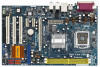
...PCI Express x16 Slot (PCIE1) 9 Clear CMOS Jumper (CLRCMOS1) 10 IDE1 Connector (IDE1, Blue) 11 SATAII Connector (SATAII_3 (PORT2); PS2 Keyboard 1.4 Motherboard Layout 1 23 4 19.1cm (7.5 in) PS2 Mouse 1 PS2_USB_PWR1 ATX12V1 56 Dual Channel DDRII533 CPU_FAN1 PARALLEL PORT Dual Core CPU Conroe DDRII_1 (64/72... Bottom: MIC IN Gigabit LAN 30 29 28 27 26 7.1CH HD LAN PHY Super I/O ` PCI EXPRESS PCIE2 PCIE3 PCIE1 ConRoe 945PL-GLAN CMOS Battery 1 CLRCMOS1 IDE1 4Mb BIOS HDMI_SPDIF1 1 AUDIO CODEC CD1 HD_AUDIO1 1 GAME1 1 PCI1 PCI2 RoHS PCI3 FLOPPY1 Intel ICH7 USB45 1 CHA_FAN1...
...PCI Express x16 Slot (PCIE1) 9 Clear CMOS Jumper (CLRCMOS1) 10 IDE1 Connector (IDE1, Blue) 11 SATAII Connector (SATAII_3 (PORT2); PS2 Keyboard 1.4 Motherboard Layout 1 23 4 19.1cm (7.5 in) PS2 Mouse 1 PS2_USB_PWR1 ATX12V1 56 Dual Channel DDRII533 CPU_FAN1 PARALLEL PORT Dual Core CPU Conroe DDRII_1 (64/72... Bottom: MIC IN Gigabit LAN 30 29 28 27 26 7.1CH HD LAN PHY Super I/O ` PCI EXPRESS PCIE2 PCIE3 PCIE1 ConRoe 945PL-GLAN CMOS Battery 1 CLRCMOS1 IDE1 4Mb BIOS HDMI_SPDIF1 1 AUDIO CODEC CD1 HD_AUDIO1 1 GAME1 1 PCI1 PCI2 RoHS PCI3 FLOPPY1 Intel ICH7 USB45 1 CHA_FAN1...

User Manual
Page 12
... the power is switched off or the power cord is an ATX form factor (12.0" x 7.5", 30.5 x 19.1 cm) motherboard. Chapter 2 Installation ConRoe945PL-GLAN is detached from the wall socket before touching any component. 2. Failure to do so may cause physical injuries to you install or ...remove any component, ensure that the motherboard fits into the holes indicated by the edges and do so may cause severe damage ...
... the power is switched off or the power cord is an ATX form factor (12.0" x 7.5", 30.5 x 19.1 cm) motherboard. Chapter 2 Installation ConRoe945PL-GLAN is detached from the wall socket before touching any component. 2. Failure to do so may cause physical injuries to you install or ...remove any component, ensure that the motherboard fits into the holes indicated by the edges and do so may cause severe damage ...
User Manual
Page 14
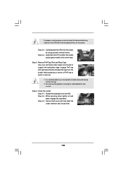
... Cap (Pick and Place Cap): Use your left hand index finger and thumb to assist in removal. 1. This cap must be placed if returning the motherboard for after service. Secure load lever with load plate tab under retention tab of the socket.
... Cap (Pick and Place Cap): Use your left hand index finger and thumb to assist in removal. 1. This cap must be placed if returning the motherboard for after service. Secure load lever with load plate tab under retention tab of the socket.

User Manual
Page 15
... oriented on side closest to the CPU fan connector on the motherboard (CPU_FAN1, see page 10, No. 6). Step 2. Step 3. Repeat with the motherboard throughholes. Step 5. Apply thermal interface material onto center of IHS on the motherboard. Place the heatsink onto the socket. Connect fan header with ... to ensure cable does not interfere with the CPU fan connector on the socket surface. 2.4 Installation of CPU Fan and Heatsink This motherboard is an example to illustrate the installation of the heatsink for 775-LAND CPU. Step 6. Then connect the CPU fan to improve ...
... oriented on side closest to the CPU fan connector on the motherboard (CPU_FAN1, see page 10, No. 6). Step 2. Step 3. Repeat with the motherboard throughholes. Step 5. Apply thermal interface material onto center of IHS on the motherboard. Place the heatsink onto the socket. Connect fan header with ... to ensure cable does not interfere with the CPU fan connector on the socket surface. 2.4 Installation of CPU Fan and Heatsink This motherboard is an example to illustrate the installation of the heatsink for 775-LAND CPU. Step 6. Then connect the CPU fan to improve ...

User Manual
Page 16
.... It will operate at single channel mode. 1. Firmly insert the DIMM into DDRII slot; Step 2. Installing a DIMM Please make sure to the motherboard and the DIMM if you force the DIMM into the slot at both ends fully snap back in the DDRII DIMM slots to activate Dual...Align a DIMM on the slot such that the notch on the DIMM matches the break on the slot. Step 3. otherwise, this motherboard and DIMM may be damaged. 2. 2.5 Installation of Memory Modules (DIMM) This motherboard provides two 240-pin DDRII (Double Data Rate) DIMM slots, and supports Dual Channel Memory Technology.
.... It will operate at single channel mode. 1. Firmly insert the DIMM into DDRII slot; Step 2. Installing a DIMM Please make sure to the motherboard and the DIMM if you force the DIMM into the slot at both ends fully snap back in the DDRII DIMM slots to activate Dual...Align a DIMM on the slot such that the notch on the DIMM matches the break on the slot. Step 3. otherwise, this motherboard and DIMM may be damaged. 2. 2.5 Installation of Memory Modules (DIMM) This motherboard provides two 240-pin DDRII (Double Data Rate) DIMM slots, and supports Dual Channel Memory Technology.

User Manual
Page 17
... the power cord is used for PCI Express cards with x16 lane width graphics cards. PCIE2 / PCIE3 (PCIE x1 slot) is completely seated on this motherboard. Step 3.
... the power cord is used for PCI Express cards with x16 lane width graphics cards. PCIE2 / PCIE3 (PCIE x1 slot) is completely seated on this motherboard. Step 3.

User Manual
Page 19
.... Primary IDE connector (Blue) (39-pin IDE1, see p.10 No. 10) PIN1 IDE1 connect the blue end connect the black end to the motherboard to the IDE devices 80-conductor ATA 66/100 cable Note: Please refer to Pin1 Note: Make sure the red-striped side of the cable...interface allows up to the SATA / SATAII hard disk or the SATAII connector on the motherboard. 19 SATAII_1 (PORT0) SATAII_3 (PORT2) SATAII_2 (PORT1) SATAII_4 (PORT3) Serial ATA (SATA) Data Cable Either end of the motherboard! Do NOT place jumper caps over the headers and connectors will cause permanent damage of ...
.... Primary IDE connector (Blue) (39-pin IDE1, see p.10 No. 10) PIN1 IDE1 connect the blue end connect the black end to the motherboard to the IDE devices 80-conductor ATA 66/100 cable Note: Please refer to Pin1 Note: Make sure the red-striped side of the cable...interface allows up to the SATA / SATAII hard disk or the SATAII connector on the motherboard. 19 SATAII_1 (PORT0) SATAII_3 (PORT2) SATAII_2 (PORT1) SATAII_4 (PORT3) Serial ATA (SATA) Data Cable Either end of the motherboard! Do NOT place jumper caps over the headers and connectors will cause permanent damage of ...

User Manual
Page 20
... module. Then connect the white end of SATA power cable to function correctly. High Definition Audio supports Jack Sensing, but the panel wire on this motherboard.
... module. Then connect the white end of SATA power cable to function correctly. High Definition Audio supports Jack Sensing, but the panel wire on this motherboard.

User Manual
Page 22
Please connect the HDMI_SPDIF connector of HDMI VGA card to the HDMI_SPDIF header on the motherboard. white end (3-pin) +5V SPDIFOUT GND blue black SPDIFOUT GND blue black SPDIFOUT GND blue black 22 Please connect the black end (A) of HDMI_SPDIF cable ...
Please connect the HDMI_SPDIF connector of HDMI VGA card to the HDMI_SPDIF header on the motherboard. white end (3-pin) +5V SPDIFOUT GND blue black SPDIFOUT GND blue black SPDIFOUT GND blue black 22 Please connect the black end (A) of HDMI_SPDIF cable ...

User Manual
Page 23
... your system. 23 Please refer to the HDMI_SPDIF connector of HDMI VGA card. (There are two white ends (2-pin and 3-pin) on this motherboard. Connect the HDMI output connector on HDMI VGA card, please refer to HDMI device, such as a digital television (DTV). For the pin definition...audio/ video source, such as a set-top box, DVD player, A/V receiver and a compatible digital audio or video monitor, such as HDTV. This motherboard is an all-digital audio/video specification, which provides SPDIF audio output to HDMI VGA card, allows the system to connect HDMI Digital TV/projector...
... your system. 23 Please refer to the HDMI_SPDIF connector of HDMI VGA card. (There are two white ends (2-pin and 3-pin) on this motherboard. Connect the HDMI output connector on HDMI VGA card, please refer to HDMI device, such as a digital television (DTV). For the pin definition...audio/ video source, such as a set-top box, DVD player, A/V receiver and a compatible digital audio or video monitor, such as HDTV. This motherboard is an all-digital audio/video specification, which provides SPDIF audio output to HDMI VGA card, allows the system to connect HDMI Digital TV/projector...

User Manual
Page 25
... Technology. 25 Then, the drivers compatible to install the SATA / SATAII hard disks. You may install SATA / SATAII hard disks on this motherboard for the possible overclocking risk before you to your optical drive first. Please refer to fixed PCI / PCIE bus. This section will show you... your system, please insert the support CD to the SATA / SATAII hard disk. Please follow the order from up to bottom side to the motherboard's SATAII connector. Therefore, the drivers you the actual CPU host frequency in the fixed mode so that supports Serial ATA (SATA) / Serial ATAII...
... Technology. 25 Then, the drivers compatible to install the SATA / SATAII hard disks. You may install SATA / SATAII hard disks on this motherboard for the possible overclocking risk before you to your optical drive first. Please refer to fixed PCI / PCIE bus. This section will show you... your system, please insert the support CD to the SATA / SATAII hard disk. Please follow the order from up to bottom side to the motherboard's SATAII connector. Therefore, the drivers you the actual CPU host frequency in the fixed mode so that supports Serial ATA (SATA) / Serial ATAII...

User Manual
Page 26
... how to use the BIOS SETUP UTILITY to get into the sub screen. 26 You may also restart by pressing the reset button on the motherboard stores the BIOS SETUP UTILITY. The BIOS FWH chip on the system chassis.
... how to use the BIOS SETUP UTILITY to get into the sub screen. 26 You may also restart by pressing the reset button on the motherboard stores the BIOS SETUP UTILITY. The BIOS FWH chip on the system chassis.

User Manual
Page 28
...cause system to malfunction. If it shows "Unlocked", you changing the ratio value of this motherboard is a read-only item, which displays whether the ratio status of this motherboard. 28 Ratio Status This is "Locked" or "Unlocked". CPU Configuration Chipset Configuration ACPI ...of Boot Failure Guard. Spread Spectrum This item should always be [Auto] for better system stability. Setting wrong values in this motherboard. BIOS SETUP UTILITY Main Advanced H/W Monitor Boot Security Exit Advanced Settings WARNING : Setting wrong values in below sections may cause the...
...cause system to malfunction. If it shows "Unlocked", you changing the ratio value of this motherboard is a read-only item, which displays whether the ratio status of this motherboard. 28 Ratio Status This is "Locked" or "Unlocked". CPU Configuration Chipset Configuration ACPI ...of Boot Failure Guard. Spread Spectrum This item should always be [Auto] for better system stability. Setting wrong values in this motherboard. BIOS SETUP UTILITY Main Advanced H/W Monitor Boot Security Exit Advanced Settings WARNING : Setting wrong values in below sections may cause the...
User Manual
Page 29
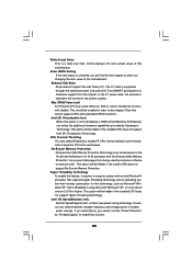
... to set to [Enabled], a VMM (Virtual Machine Architecture) can utilize the additional hardware capabilities provided by malicious software to enable this motherboard. Intel (R) SpeedStep(tm) tech. Ratio Actual Value This is a read-only item, which displays the ratio actual value of the system...of this option is supported through the native processor instructions HLT and MWAIT and requires no hardware support from overheated. When this motherboard. The C1 state is set the "Power Schemes" as Microsoft® Windows® XP. Enhance Halt State All processors support...
... to set to [Enabled], a VMM (Virtual Machine Architecture) can utilize the additional hardware capabilities provided by malicious software to enable this motherboard. Intel (R) SpeedStep(tm) tech. Ratio Actual Value This is a read-only item, which displays the ratio actual value of the system...of this option is supported through the native processor instructions HLT and MWAIT and requires no hardware support from overheated. When this motherboard. The C1 state is set the "Power Schemes" as Microsoft® Windows® XP. Enhance Halt State All processors support...

User Manual
Page 30
... you adjusting them. Flexibility Option The default value of memory accessing. DRAM RAS# Precharge This controls the idle clocks after a precharge command is selected, the motherboard will configure the following items by SPD [Enabled] DRAM CAS# Latency [Auto] Boot Graphic Adapter Priority [PCI/PCIE] OnBoard HD Audio Front Panel Control OnBoard...
... you adjusting them. Flexibility Option The default value of memory accessing. DRAM RAS# Precharge This controls the idle clocks after a precharge command is selected, the motherboard will configure the following items by SPD [Enabled] DRAM CAS# Latency [Auto] Boot Graphic Adapter Priority [PCI/PCIE] OnBoard HD Audio Front Panel Control OnBoard...

