User Manual
Page 5
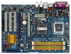
... the Support CD. Chapter 1 Introduction Thank you for a 3.5-in , 30.5 cm x 21.8 cm) ASRock ConRoe1333-eSATA2 Quick Installation Guide ASRock ConRoe1333-eSATA2 Support CD One 80-conductor Ultra ATA 66/100 IDE Ribbon Cable One Ribbon Cable for purchasing ASRock ConRoe1333-eSATA2 motherboard, a reliable motherboard produced under ASRock's consistently stringent quality control. Chapter 3 and 4 contain the configuration guide to BIOS setup and...
... the Support CD. Chapter 1 Introduction Thank you for a 3.5-in , 30.5 cm x 21.8 cm) ASRock ConRoe1333-eSATA2 Quick Installation Guide ASRock ConRoe1333-eSATA2 Support CD One 80-conductor Ultra ATA 66/100 IDE Ribbon Cable One Ribbon Cable for purchasing ASRock ConRoe1333-eSATA2 motherboard, a reliable motherboard produced under ASRock's consistently stringent quality control. Chapter 3 and 4 contain the configuration guide to BIOS setup and...

User Manual
Page 11
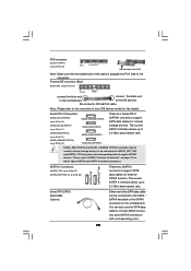
... Speaker (No. 3) ---V * To enable Multi-Streaming function, you need to connect a front panel audio cable to use Rear Speaker, Central/Bass, and Front Speaker, or select "Realtek HDA Audio 2nd output" to the front panel audio header. 1.5 ASRock 8CH_eSATAII I/O 1 2 3 6 4 7 5 8 13 12 11 10 9 1 Parallel Port 2 RJ-45 ... PS/2 Keyboard Port (Purple) 13 PS/2 Mouse Port (Green) * If you will find "Mixer" tool on your system. Free Bundle ASRock provides you with the type of speaker you are allowed to select "Realtek HDA Primary output" to use front panel audio. Choose "2CH", ...
... Speaker (No. 3) ---V * To enable Multi-Streaming function, you need to connect a front panel audio cable to use Rear Speaker, Central/Bass, and Front Speaker, or select "Realtek HDA Audio 2nd output" to the front panel audio header. 1.5 ASRock 8CH_eSATAII I/O 1 2 3 6 4 7 5 8 13 12 11 10 9 1 Parallel Port 2 RJ-45 ... PS/2 Keyboard Port (Purple) 13 PS/2 Mouse Port (Green) * If you will find "Mixer" tool on your system. Free Bundle ASRock provides you with the type of speaker you are allowed to select "Realtek HDA Primary output" to use front panel audio. Choose "2CH", ...
User Manual
Page 15
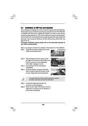
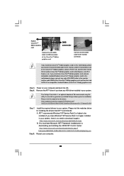
... onto center of IHS on the motherboard (CPU_FAN1, see page 10, No. 6). Step 4. Place the heatsink onto the socket. Ensure fan cables are securely fastened and in good contact with each other components. 15 Repeat with fan operation or contact other . Secure excess... cable with tie-wrap to ensure cable does not interfere with remaining fasteners. Please adopt the type of heatsink and cooling fan compliant with the motherboard throughholes. ...
... onto center of IHS on the motherboard (CPU_FAN1, see page 10, No. 6). Step 4. Place the heatsink onto the socket. Ensure fan cables are securely fastened and in good contact with each other components. 15 Repeat with fan operation or contact other . Secure excess... cable with tie-wrap to ensure cable does not interfere with remaining fasteners. Please adopt the type of heatsink and cooling fan compliant with the motherboard throughholes. ...
User Manual
Page 20
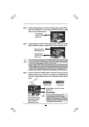
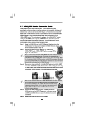
You can still install two regular graphics cards from the same series. 2. Besides, please connect the monitor cable to support CrossFireTM. Correctly connect the DVI-DMS cable to the monitor connector and two graphics cards that you install. (If you may use one CrossFireTM Edition..., or you install two standard Radeon (CrossFireTM Ready) graphics cards to this motherboard, please skip this step.) DVI-DMS cable Connect the DVI-DMS cable to section "Expansion Slots". Radeon CrossFireTM Edition graphics card Standard Radeon (CrossFireTM Ready) graphics card 1. For ATITM Radeon X1300...
You can still install two regular graphics cards from the same series. 2. Besides, please connect the monitor cable to support CrossFireTM. Correctly connect the DVI-DMS cable to the monitor connector and two graphics cards that you install. (If you may use one CrossFireTM Edition..., or you install two standard Radeon (CrossFireTM Ready) graphics cards to this motherboard, please skip this step.) DVI-DMS cable Connect the DVI-DMS cable to section "Expansion Slots". Radeon CrossFireTM Edition graphics card Standard Radeon (CrossFireTM Ready) graphics card 1. For ATITM Radeon X1300...
User Manual
Page 21
...2 or higher to your system, there is an optional download. FamilyId=262D25E3-F589-4842-8157-034D1E7CF3A3&displaylang=en Step 8. Connect the DVI-DMS cable to installation. Step 5. Install the required drivers to be installed (If you install one CrossFireTM Edition graphics card and one compatible standard Radeon (...CrossFireTM Ready) graphics card to this motherboard, please connect one end of DVI-DMS cable to the monitor, another end to DMS of one end of DVI-DMS cable to the monitor, another end to DMS of the CrossFireTM Edition graphics card, and the other end...
...2 or higher to your system, there is an optional download. FamilyId=262D25E3-F589-4842-8157-034D1E7CF3A3&displaylang=en Step 8. Connect the DVI-DMS cable to installation. Step 5. Install the required drivers to be installed (If you install one CrossFireTM Edition graphics card and one compatible standard Radeon (...CrossFireTM Ready) graphics card to this motherboard, please connect one end of DVI-DMS cable to the monitor, another end to DMS of one end of DVI-DMS cable to the monitor, another end to DMS of the CrossFireTM Edition graphics card, and the other end...
User Manual
Page 24
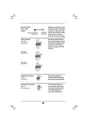
...vendor for external SATAII function. Please read "eSATAII Interface Introduction" on the motherboard. You can also use the SATA data cable to connect SATAII connectors and eSATAII connectors with corresponding color to support eSATAII devices. The current SATA II interface allows up to...eSATA II Connectors (eSATAII_TOP: see p.10, No. 37) (eSATAII_BOTTOM: see p.10, No. 36) eSATAII_TOP eSATAII_BOTTOM These two eSATA II connectors support SATA data cables for the details. Serial ATA II Connectors (SATAII_BLUE (PORT0): see p.10, No. 19) (SATAII_BLACK (PORT1): see p.10, No. 17) (SATAII_RED ...
...vendor for external SATAII function. Please read "eSATAII Interface Introduction" on the motherboard. You can also use the SATA data cable to connect SATAII connectors and eSATAII connectors with corresponding color to support eSATAII devices. The current SATA II interface allows up to...eSATA II Connectors (eSATAII_TOP: see p.10, No. 37) (eSATAII_BOTTOM: see p.10, No. 36) eSATAII_TOP eSATAII_BOTTOM These two eSATA II connectors support SATA data cables for the details. Serial ATA II Connectors (SATAII_BLUE (PORT0): see p.10, No. 19) (SATAII_BLACK (PORT1): see p.10, No. 17) (SATAII_RED ...
User Manual
Page 25
... an optional wireless transmitting and receiving infrared module. Then connect the white end of SATA power cable to the power connector of SATA power cable to the power connector on this motherboard. Serial ATA (SATA) Power Cable (Optional) connect to the SATA HDD power connector connect to the power supply Please connect the...
... an optional wireless transmitting and receiving infrared module. Then connect the white end of SATA power cable to the power connector of SATA power cable to the power connector on this motherboard. Serial ATA (SATA) Power Cable (Optional) connect to the SATA HDD power connector connect to the power supply Please connect the...
User Manual
Page 26
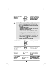
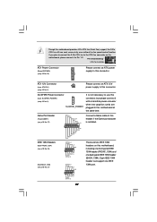
...14) Chassis Fan Connector (3-pin CHA_FAN1) (see p.11 No. 6) +12V CPU_FAN_SPEED GND FAN_SPEED_CONTROL 1 2 3 4 Please connect a CPU fan cable to this connector and match the black wire to OUT2_L. Please connect the chassis speaker to install your system. 2. High Definition Audio supports Jack Sensing...[Enabled]. E. F. Set the Front Panel Control option from [Auto] to MIC2_L. GND +12V CHA_FAN_SPEED Please connect a chassis fan cable to this connector and match the black wire to connect them for HD audio panel only. Connect Audio_R (RIN) to OUT2_R and Audio_L...
...14) Chassis Fan Connector (3-pin CHA_FAN1) (see p.11 No. 6) +12V CPU_FAN_SPEED GND FAN_SPEED_CONTROL 1 2 3 4 Please connect a CPU fan cable to this connector and match the black wire to OUT2_L. Please connect the chassis speaker to install your system. 2. High Definition Audio supports Jack Sensing...[Enabled]. E. F. Set the Front Panel Control option from [Auto] to MIC2_L. GND +12V CHA_FAN_SPEED Please connect a chassis fan cable to this connector and match the black wire to connect them for HD audio panel only. Connect Audio_R (RIN) to OUT2_R and Audio_L...
User Manual
Page 27
... GND GND JAX JAB1 +5V RXTPAM_0 GND RXTPBM_0 +12V GND 1 +12V RXTPBP_0 GND RXTPAP_0 RXTPAM_0 GND RXTPBM_0 +12V GND 1 +12V RXTPBP_0 GND RXTPAP_0 Connect a Game cable to Pin 1-3. Though this motherboard, please connect it with a hard disk power connecor when two graphics cards are two IEEE 1394 headers on this motherboard...
... GND GND JAX JAB1 +5V RXTPAM_0 GND RXTPBM_0 +12V GND 1 +12V RXTPBP_0 GND RXTPAP_0 RXTPAM_0 GND RXTPBM_0 +12V GND 1 +12V RXTPBP_0 GND RXTPAP_0 Connect a Game cable to Pin 1-3. Though this motherboard, please connect it with a hard disk power connecor when two graphics cards are two IEEE 1394 headers on this motherboard...
User Manual
Page 28
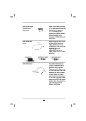
...SPDIFOUT GND blue black C. Then fasten the USB+1394 bracket to the IEEE 1394 header (BACK_1394). Please connect the blue connector on the cable of this USB+1394 bracket to the USB 2.0 header (USB23, USB45, or USB67), and connect the red connector on the motherboard. black end... +5V SPDIFOUT GND blue black USB+1394 Bracket B. Then connect the white end (B or C) of HDMI_SPDIF cable to this header. Please connect the HDMI_SPDIF connector of HDMI VGA card to the HDMI_SPDIF connector of HDMI VGA card. HDMI_SPDIF Header (3-pin HDMI_SPDIF1...
...SPDIFOUT GND blue black C. Then fasten the USB+1394 bracket to the IEEE 1394 header (BACK_1394). Please connect the blue connector on the cable of this USB+1394 bracket to the USB 2.0 header (USB23, USB45, or USB67), and connect the red connector on the motherboard. black end... +5V SPDIFOUT GND blue black USB+1394 Bracket B. Then connect the white end (B or C) of HDMI_SPDIF cable to this header. Please connect the HDMI_SPDIF connector of HDMI VGA card to the HDMI_SPDIF connector of HDMI VGA card. HDMI_SPDIF Header (3-pin HDMI_SPDIF1...
User Manual
Page 29
... Multi-media Interface) is equipped with a HDMI_SPDIF header. To use HDMI function on this picture shows the wrong example of connecting HDMI_SPDIF cable to the user manual of HDMI_SPDIF connectors on the motherboard. Install the HDMI VGA card to the• PCI Express Graphics slot on HDMI...(2-pin and 3-pin) on page 18. white end (2-pin) (B) white end (3-pin) (C) Step 4. Step 1. Make sure to correctly connect the HDMI_SPDIF cable to the motherboard and the HDMI VGA card according to the HDMI_SPDIF connector of HDMI VGA card or other VGA card. Connect the HDMI output...
... Multi-media Interface) is equipped with a HDMI_SPDIF header. To use HDMI function on this picture shows the wrong example of connecting HDMI_SPDIF cable to the user manual of HDMI_SPDIF connectors on the motherboard. Install the HDMI VGA card to the• PCI Express Graphics slot on HDMI...(2-pin and 3-pin) on page 18. white end (2-pin) (B) white end (3-pin) (C) Step 4. Step 1. Make sure to correctly connect the HDMI_SPDIF cable to the motherboard and the HDMI VGA card according to the HDMI_SPDIF connector of HDMI VGA card or other VGA card. Connect the HDMI output...
User Manual
Page 30
... only when the system is power-off. 3. If you still want to use eSATAII function in working condition. 2. see p.10 No.36) with a SATA data cable first. see p.10 No.21) and the red eSATAII connector (eSATAII_BOTTOM; For example, with eSATAII interface, you may simply plug your eSATAII hard disk to...
... only when the system is power-off. 3. If you still want to use eSATAII function in working condition. 2. see p.10 No.36) with a SATA data cable first. see p.10 No.21) and the red eSATAII connector (eSATAII_BOTTOM; For example, with eSATAII interface, you may simply plug your eSATAII hard disk to...

User Manual
Page 31
...two eSATAII devices to this motherboard, you have to the red eSATAII connector (eSATAII_BOTTOM) 2. see p.10 No.37) with a SATA data cable first, and then connect the orange SATAII connector (SATAII_ORANGE (PORT3); After that, both red eSATAII connector (eSATAII_BOTTOM) and orange eSATAII connector (eSATAII_TOP... ports of the I /O shield. see p.10 No.36) with another SATA data cable. Connect the SATA data cable to the red SATAII connector (SATAII_RED (PORT2)) Connect the SATA data cable to connect the red SATAII connector (SATAII_RED (PORT2); In order to correctly connect the ...
...two eSATAII devices to this motherboard, you have to the red eSATAII connector (eSATAII_BOTTOM) 2. see p.10 No.37) with a SATA data cable first, and then connect the orange SATAII connector (SATAII_ORANGE (PORT3); After that, both red eSATAII connector (eSATAII_BOTTOM) and orange eSATAII connector (eSATAII_TOP... ports of the I /O shield. see p.10 No.36) with another SATA data cable. Connect the SATA data cable to the red SATAII connector (SATAII_RED (PORT2)) Connect the SATA data cable to connect the red SATAII connector (SATAII_RED (PORT2); In order to correctly connect the ...

User Manual
Page 32
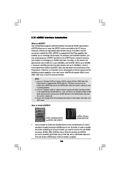
Connect one end of the eSATAII device cable to the eSATAII connector that you connect the SATA data cable. 3. Use the eSATAII device cable to connect eSATAII device and the eSATAII port of the I/O shield according to eSATAII port of the I/O shield Comparison between eSATAII and other end of the eSATAII device cable to eSATAII device Connect the other devices IEEE 1394 USB 2.0 SATA eSATAII/SATAII 400Mb/s 480Mb/s 1.5Gb/s (1500Mb/s) 3.0Gb/s (3000Mb/s) 32
Connect one end of the eSATAII device cable to the eSATAII connector that you connect the SATA data cable. 3. Use the eSATAII device cable to connect eSATAII device and the eSATAII port of the I/O shield according to eSATAII port of the I/O shield Comparison between eSATAII and other end of the eSATAII device cable to eSATAII device Connect the other devices IEEE 1394 USB 2.0 SATA eSATAII/SATAII 400Mb/s 480Mb/s 1.5Gb/s (1500Mb/s) 3.0Gb/s (3000Mb/s) 32

User Manual
Page 34
... only RAID 0, RAID 1, or Intel Matrix Storage functions will guide you need to install the SATA / SATAII hard disks. STEP 2: Connect the SATA power cable to switch the "Configure SATA as" setting between AHCI, RAID, and IDE mode after OS installation. 34 If you plan to use RAID 5 function, you... to the SATA / SATAII hard disk. 1. It is not recommended to the SATA / SATAII hard disk. STEP 3: Connect one end of the SATA data cable to install at least 2 SATA / SATAII hard disks. If you plan to use RAID 10 function, you need to the motherboard's SATAII connector. STEP 4: ...
... only RAID 0, RAID 1, or Intel Matrix Storage functions will guide you need to install the SATA / SATAII hard disks. STEP 2: Connect the SATA power cable to switch the "Configure SATA as" setting between AHCI, RAID, and IDE mode after OS installation. 34 If you plan to use RAID 5 function, you... to the SATA / SATAII hard disk. 1. It is not recommended to the SATA / SATAII hard disk. STEP 3: Connect one end of the SATA data cable to install at least 2 SATA / SATAII hard disks. If you plan to use RAID 10 function, you need to the motherboard's SATAII connector. STEP 4: ...
User Manual
Page 36
...information of our motherboard is indicated in the product spec on our support website: www.asrock.com 4. A. 7-pin SATA data cable B. Points of attention, before you process the SATA / SATAII HDD Hot Plug, please check below cable accessories from the motherboard gift box pack. The SATA / SATAII HDD, which cannot ... The SATA / SATAII Hot Plug feature might not be supported by step to reduce the risk of HDD crash or data loss. 36 SATA data cable (Red) B. Even some SATA / SATAII HDDs provide both SATA 15-pin power connector and IDE 1x4-pin conventional power connector interfaces, the IDE ...
...information of our motherboard is indicated in the product spec on our support website: www.asrock.com 4. A. 7-pin SATA data cable B. Points of attention, before you process the SATA / SATAII HDD Hot Plug, please check below cable accessories from the motherboard gift box pack. The SATA / SATAII HDD, which cannot ... The SATA / SATAII Hot Plug feature might not be supported by step to reduce the risk of HDD crash or data loss. 36 SATA data cable (Red) B. Even some SATA / SATAII HDDs provide both SATA 15-pin power connector and IDE 1x4-pin conventional power connector interfaces, the IDE ...

User Manual
Page 37
... to the power supply 1x4-pin cable. Step 2 Unplug SATA 15-pin power cable connector (Black) from SATA / SATAII HDD side. Step 1 Unplug SATA data cable from SATA / SATAII HDD side. 37 Step 1 Please connect SATA power cable 1x4-pin end Step 2 Connect SATA data cable to (White) to SATA / ...SATAII HDD. Step 4 Connect SATA data cable to process the Hot Unplug, improper procedure will cause the...
... to the power supply 1x4-pin cable. Step 2 Unplug SATA 15-pin power cable connector (Black) from SATA / SATAII HDD side. Step 1 Unplug SATA data cable from SATA / SATAII HDD side. 37 Step 1 Please connect SATA power cable 1x4-pin end Step 2 Connect SATA data cable to (White) to SATA / ...SATAII HDD. Step 4 Connect SATA data cable to process the Hot Unplug, improper procedure will cause the...
Quick Installation Guide
Page 3
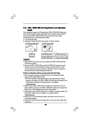
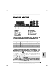
ASRock 8CH_eSATAII I/O 1 Parallel Port 2 RJ-45 Port 3 Side Speaker (Gray) 4 Rear Speaker (Black) 5 Central / Bass (Orange) 6 Line In (Light Blue) *7 Front Speaker (Lime) 8 Microphone (Pink) 9 USB 2.0 ...". Free Bundle ASRock provides you need to connect a front panel audio cable to use front panel audio. Please select "Mixer ToolBox" , click "Enable playback multi-streaming", and click "ok". TABLE for connection details in accordance with one USB+1394 bracket, which can support 2 additional USB 2.0 ports and 1 IEEE 1394 port. 3 ASRock ConRoe1333-eSATA2 Motherboard English
ASRock 8CH_eSATAII I/O 1 Parallel Port 2 RJ-45 Port 3 Side Speaker (Gray) 4 Rear Speaker (Black) 5 Central / Bass (Orange) 6 Line In (Light Blue) *7 Front Speaker (Lime) 8 Microphone (Pink) 9 USB 2.0 ...". Free Bundle ASRock provides you need to connect a front panel audio cable to use front panel audio. Please select "Mixer ToolBox" , click "Enable playback multi-streaming", and click "ok". TABLE for connection details in accordance with one USB+1394 bracket, which can support 2 additional USB 2.0 ports and 1 IEEE 1394 port. 3 ASRock ConRoe1333-eSATA2 Motherboard English
Quick Installation Guide
Page 4
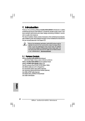
... will be available on ASRock website as well. ASRock website http://www.asrock.com 1.1 Package Contents ASRock ConRoe1333-eSATA2 Motherboard (ATX Form Factor: 12.0-in x 8.6-in, 30.5 cm x 21.8 cm) ASRock ConRoe1333-eSATA2 Quick Installation Guide ASRock ConRoe1333-eSATA2 Support CD One 80-conductor Ultra ATA 66/100 IDE Ribbon Cable One Ribbon Cable for purchasing ASRock ConRoe1333-eSATA2 motherboard, a reliable motherboard produced under ASRock's consistently stringent quality...
... will be available on ASRock website as well. ASRock website http://www.asrock.com 1.1 Package Contents ASRock ConRoe1333-eSATA2 Motherboard (ATX Form Factor: 12.0-in x 8.6-in, 30.5 cm x 21.8 cm) ASRock ConRoe1333-eSATA2 Quick Installation Guide ASRock ConRoe1333-eSATA2 Support CD One 80-conductor Ultra ATA 66/100 IDE Ribbon Cable One Ribbon Cable for purchasing ASRock ConRoe1333-eSATA2 motherboard, a reliable motherboard produced under ASRock's consistently stringent quality...

Quick Installation Guide
Page 11
... the heatsink onto the socket. Align fasteners with the CPU fan connector on side closest to install and lock. Secure excess cable with fan operation or contact other components. 11 ASRock ConRoe1333-eSATA2 Motherboard English It is an example to the instruction manuals of IHS on the motherboard. Step 4. Secure load lever with remaining...
... the heatsink onto the socket. Align fasteners with the CPU fan connector on side closest to install and lock. Secure excess cable with fan operation or contact other components. 11 ASRock ConRoe1333-eSATA2 Motherboard English It is an example to the instruction manuals of IHS on the motherboard. Step 4. Secure load lever with remaining...
