
User Manual
Page 3
... CPU Installation 14 2.2 Installation of CPU Fan and Heatsink 14 2.3 Installation of Memory Modules (DIMM 15 2.4 Expansion Slots (PCI Express, PCI, and HDMR Slots 17 2.5 Easy Dual Monitor Feature (ALiveNF6G-DVI 18 2.6 Easy Multi Monitor Feature (ALiveNF6G-DVI / ALiveNF6G-VSTA...12 Hot Plug and Hot Swap Functions for Windows® VistaTM Premium and Basic Logo 9 1.4 Motherboard Layout (ALiveNF6G-DVI 10 1.5 Motherboard Layout (ALiveNF6G-VSTA 11 1.6 HD 8CH I/O (ALiveNF6G-DVI / ALiveNF6G-VSTA 12 2 . Contents 1 . BIOS SETUP UTILITY 32 3.1 Introduction 32 3.1.1 BIOS Menu Bar 32 3.1.2 ...
... CPU Installation 14 2.2 Installation of CPU Fan and Heatsink 14 2.3 Installation of Memory Modules (DIMM 15 2.4 Expansion Slots (PCI Express, PCI, and HDMR Slots 17 2.5 Easy Dual Monitor Feature (ALiveNF6G-DVI 18 2.6 Easy Multi Monitor Feature (ALiveNF6G-DVI / ALiveNF6G-VSTA...12 Hot Plug and Hot Swap Functions for Windows® VistaTM Premium and Basic Logo 9 1.4 Motherboard Layout (ALiveNF6G-DVI 10 1.5 Motherboard Layout (ALiveNF6G-VSTA 11 1.6 HD 8CH I/O (ALiveNF6G-DVI / ALiveNF6G-VSTA 12 2 . Contents 1 . BIOS SETUP UTILITY 32 3.1 Introduction 32 3.1.1 BIOS Menu Bar 32 3.1.2 ...

User Manual
Page 4
3.2 Main Screen 33 3.3 Advanced Screen 34 3.3.1 CPU Configuration 35 3.3.2 Chipset Configuration 38 3.3.3 ACPI Configuration 39 3.3.4 IDE Configuration 40 3.3.5 PCIPnP Configuration 42 3.3.6 Floppy Configuration 43 3.3.7 Super IO Configuration 43 3.3.8 USB Configuration 44 3.4 Hardware ...
3.2 Main Screen 33 3.3 Advanced Screen 34 3.3.1 CPU Configuration 35 3.3.2 Chipset Configuration 38 3.3.3 ACPI Configuration 39 3.3.4 IDE Configuration 40 3.3.5 PCIPnP Configuration 42 3.3.6 Floppy Configuration 43 3.3.7 Super IO Configuration 43 3.3.8 USB Configuration 44 3.4 Hardware ...
User Manual
Page 5
... and CPU support lists on ASRock website without notice. Chapter 3 and 4 contain the configuration guide to BIOS setup and information of this manual will be subject to quality and endurance. Introduction Thank you for ALiveNF6G-DVI) 5 ASRock website http://www.asrock.com 1.1 Package Contents 1 x ASRock ALiveNF6G-DVI / ALiveNF6G-VSTA Motherboard (Micro ATX Form Factor: 9.6-in x 9.6-in, 24.4 cm x 24.4 cm) 1 x ASRock ALiveNF6G-DVI / ALiveNF6G...
... and CPU support lists on ASRock website without notice. Chapter 3 and 4 contain the configuration guide to BIOS setup and information of this manual will be subject to quality and endurance. Introduction Thank you for ALiveNF6G-DVI) 5 ASRock website http://www.asrock.com 1.1 Package Contents 1 x ASRock ALiveNF6G-DVI / ALiveNF6G-VSTA Motherboard (Micro ATX Form Factor: 9.6-in x 9.6-in, 24.4 cm x 24.4 cm) 1 x ASRock ALiveNF6G-DVI / ALiveNF6G...
User Manual
Page 6
... 3.0 - Gigabit LAN 10/100/1000 Mb/s (ALiveNF6G-DVI) - Speed: 10/100 Ethernet (ALiveNF6G-VSTA) - Supports AMD's Cool 'n' QuietTM Technology (see CAUTION 3) - NVIDIA® GeForce 6100 / nForce 430 or GeForce 6150SE / nForce 430 (see CAUTION 1) - ASRock U-COP (see CAUTION 8) - 2 x PCI...and Sempron Processors - Max. Boot Failure Guard (B.F.G.) - Max. Giga PHY Realtek RTL8211B (ALiveNF6G-DVI) - capacity: 8GB (see CAUTION 2) - Dual Channel DDRII Memory Technology (see CAUTION 6) - CPU Frequency Stepless Control (see CAUTION 4) - 4 x DDRII DIMM slots - Integrated NVIDIA&#...
... 3.0 - Gigabit LAN 10/100/1000 Mb/s (ALiveNF6G-DVI) - Speed: 10/100 Ethernet (ALiveNF6G-VSTA) - Supports AMD's Cool 'n' QuietTM Technology (see CAUTION 3) - NVIDIA® GeForce 6100 / nForce 430 or GeForce 6150SE / nForce 430 (see CAUTION 1) - ASRock U-COP (see CAUTION 8) - 2 x PCI...and Sempron Processors - Max. Boot Failure Guard (B.F.G.) - Max. Giga PHY Realtek RTL8211B (ALiveNF6G-DVI) - capacity: 8GB (see CAUTION 2) - Dual Channel DDRII Memory Technology (see CAUTION 6) - CPU Frequency Stepless Control (see CAUTION 4) - 4 x DDRII DIMM slots - Integrated NVIDIA&#...

User Manual
Page 7
...Certifications - 1 x VGA Port - 1 x Parallel Port (ECP/EPP Support) - 4 x Ready-to-Use USB 2.0 Ports - 1 x RJ-45 Port - Supports jumperfree - CPU Internal Temperature Sensing - CPU Quiet Fan - FCC, CE, Microsoft® WHQL Certificated 7 CD in /Front Speaker/Microphone (see CAUTION 9) - 4 x Serial ATAII 3.0Gb/s connectors, support RAID (RAID 0,... Monitoring: +12V, +5V, +3.3V, Vcore - Front panel audio connector - 3 x USB 2.0 headers (support 6 USB 2.0 ports) (see CAUTION 12) - Chassis Fan Tachometer - CPU/Chassis FAN connector - 20 pin ATX power connector - 4 pin 12V power connector...
...Certifications - 1 x VGA Port - 1 x Parallel Port (ECP/EPP Support) - 4 x Ready-to-Use USB 2.0 Ports - 1 x RJ-45 Port - Supports jumperfree - CPU Internal Temperature Sensing - CPU Quiet Fan - FCC, CE, Microsoft® WHQL Certificated 7 CD in /Front Speaker/Microphone (see CAUTION 9) - 4 x Serial ATAII 3.0Gb/s connectors, support RAID (RAID 0,... Monitoring: +12V, +5V, +3.3V, Vcore - Front panel audio connector - 3 x USB 2.0 headers (support 6 USB 2.0 ports) (see CAUTION 12) - Chassis Fan Tachometer - CPU/Chassis FAN connector - 20 pin ATX power connector - 4 pin 12V power connector...
User Manual
Page 8
...and expense. To improve heat dissipation, remember to read "Untied Overclocking Technology" on page 15 for details. 3. This motherboard supports ASRock AM2 Boost overclocking technology. If your system. CAUTION! 1. Enabling this motherboard offers stepless control, it may not be applicative to...BIOS, applying Untied Overclocking Technology, or using the thirdparty overclocking tools. Although this function will be less than the recommended CPU bus frequencies may be GeForce 6150SE / nForce 430 instead of memory modules on page 31 for proper installation. 5. ...
...and expense. To improve heat dissipation, remember to read "Untied Overclocking Technology" on page 15 for details. 3. This motherboard supports ASRock AM2 Boost overclocking technology. If your system. CAUTION! 1. Enabling this motherboard offers stepless control, it may not be applicative to...BIOS, applying Untied Overclocking Technology, or using the thirdparty overclocking tools. Although this function will be less than the recommended CPU bus frequencies may be GeForce 6150SE / nForce 430 instead of memory modules on page 31 for proper installation. 5. ...
User Manual
Page 9
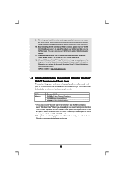
... http://www.asrock.com 1.3 Minimum Hardware Requirement Table for Windows® VistaTM Premium and Basic Logo For system integrators and users who purchase this motherboard, please refer to our website in the future. CPU Memory Sempron 2800+ 512MB x 2 Dual Channel (Premium) 512MB Single Channel (Basic)... proper connection. 10. As long as we have the latest driver, we will update it to Premium Discrete requirement at http://www.asrock.com 9 For microphone input, this motherboard supports 2-channel, 4-channel, 6-channel, and 8-channel modes. Power Management for Microsoft®...
... http://www.asrock.com 1.3 Minimum Hardware Requirement Table for Windows® VistaTM Premium and Basic Logo For system integrators and users who purchase this motherboard, please refer to our website in the future. CPU Memory Sempron 2800+ 512MB x 2 Dual Channel (Premium) 512MB Single Channel (Basic)... proper connection. 10. As long as we have the latest driver, we will update it to Premium Discrete requirement at http://www.asrock.com 9 For microphone input, this motherboard supports 2-channel, 4-channel, 6-channel, and 8-channel modes. Power Management for Microsoft®...
User Manual
Page 10
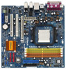
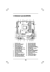
... x 240-pin DDRII DIMM Slots (Dual Channel B: DDRII_3, DDRII_4; 1.4 Motherboard Layout (ALiveNF6G-DVI) 1 2 34 5 67 8 24.4cm (9.6-in) PS2 Keyboard PS2 Mouse 1 PS2_USB_PW1 ATX12V1 CPU_FAN1 IR1 1 9 Super I/O GAME1 1 Dual Core CPU Dual Channel PARALLEL PORT DDRII_3 (64/72 bit, 240F-pSinBm8o0d0ule) DDRII_4 (64/72 bit,...Top: LINE IN Center: FRONT Bottom: MIC IN LAN PHY CD1 AUDIO CODEC HDMI_SPDIF1 1 1 HD_AUDIO1 ` PCIE1 PCI EXPRESS RAID ALiveNF6G-DVI PCI1 PCI2 PCIE2 7.1CH HD HDMR1 CMOS BATTERY CLRCMOS1 1 NVIDIA GeForce 6100 / nForce 430 or GeForce 6150SE / nForce 430 ...
... x 240-pin DDRII DIMM Slots (Dual Channel B: DDRII_3, DDRII_4; 1.4 Motherboard Layout (ALiveNF6G-DVI) 1 2 34 5 67 8 24.4cm (9.6-in) PS2 Keyboard PS2 Mouse 1 PS2_USB_PW1 ATX12V1 CPU_FAN1 IR1 1 9 Super I/O GAME1 1 Dual Core CPU Dual Channel PARALLEL PORT DDRII_3 (64/72 bit, 240F-pSinBm8o0d0ule) DDRII_4 (64/72 bit,...Top: LINE IN Center: FRONT Bottom: MIC IN LAN PHY CD1 AUDIO CODEC HDMI_SPDIF1 1 1 HD_AUDIO1 ` PCIE1 PCI EXPRESS RAID ALiveNF6G-DVI PCI1 PCI2 PCIE2 7.1CH HD HDMR1 CMOS BATTERY CLRCMOS1 1 NVIDIA GeForce 6100 / nForce 430 or GeForce 6150SE / nForce 430 ...

User Manual
Page 11
...24 Clear CMOS Jumper (CLRCMOS1) (Dual Channel B: DDRII_3, DDRII_4; 1.5 Motherboard Layout (ALiveNF6G-VSTA) 1 2 34 5 67 8 24.4cm (9.6-in) PS2 Keyboard PS2 Mouse 1 PS2_USB_PW1 ATX12V1 CPU_FAN1 IR1 1 9 Super I/O GAME1 1 Dual Core CPU Dual Channel PARALLEL PORT DDRII_3 (64/72 bit, 240F-pSinBm8o0d0ule) DDRII_4 (64/72 bit... Top: LINE IN Center: FRONT Bottom: MIC IN LAN PHY CD1 AUDIO CODEC HDMI_SPDIF1 1 1 HD_AUDIO1 ` PCIE1 PCI EXPRESS RAID ALiveNF6G-VSTA PCI1 PCI2 PCIE2 7.1CH HD HDMR1 CMOS BATTERY CLRCMOS1 1 NVIDIA GeForce 6100 / nForce 430 or GeForce 6150SE / nForce 430...
...24 Clear CMOS Jumper (CLRCMOS1) (Dual Channel B: DDRII_3, DDRII_4; 1.5 Motherboard Layout (ALiveNF6G-VSTA) 1 2 34 5 67 8 24.4cm (9.6-in) PS2 Keyboard PS2 Mouse 1 PS2_USB_PW1 ATX12V1 CPU_FAN1 IR1 1 9 Super I/O GAME1 1 Dual Core CPU Dual Channel PARALLEL PORT DDRII_3 (64/72 bit, 240F-pSinBm8o0d0ule) DDRII_4 (64/72 bit... Top: LINE IN Center: FRONT Bottom: MIC IN LAN PHY CD1 AUDIO CODEC HDMI_SPDIF1 1 1 HD_AUDIO1 ` PCIE1 PCI EXPRESS RAID ALiveNF6G-VSTA PCI1 PCI2 PCIE2 7.1CH HD HDMR1 CMOS BATTERY CLRCMOS1 1 NVIDIA GeForce 6100 / nForce 430 or GeForce 6150SE / nForce 430...
User Manual
Page 14
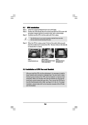
... fastened and in place. The lever clicks on the socket while you install the CPU into this motherboard, it firmly on the side tab to secure the CPU. Position the CPU directly above the socket such that the CPU corner with the golden triangle matches the socket corner with each other. Step 2. ...The CPU fits only in place, press it is locked. DO NOT force the CPU into the socket until it is necessary...
... fastened and in place. The lever clicks on the socket while you install the CPU into this motherboard, it firmly on the side tab to secure the CPU. Position the CPU directly above the socket such that the CPU corner with the golden triangle matches the socket corner with each other. Step 2. ...The CPU fits only in place, press it is locked. DO NOT force the CPU into the socket until it is necessary...
User Manual
Page 24
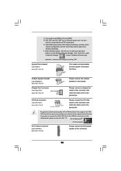
... SPEAKER DUMMY DUMMY +5V Chassis Fan Connector (3-pin CHA_FAN1) (see p.10/p.11 No. 32) Please connect an ATX power supply to this motherboard provides 4-Pin CPU fan (Quiet Fan) support, the 3-Pin CPU fan still can work successfully even without the fan speed control function. If you plan to connect the 3-Pin... CPU fan to the CPU fan connector on the lower right hand taskbar to Ground (GND). Enter BIOS Setup Utility. Set the Front Panel Control option from [Auto] ...
... SPEAKER DUMMY DUMMY +5V Chassis Fan Connector (3-pin CHA_FAN1) (see p.10/p.11 No. 32) Please connect an ATX power supply to this motherboard provides 4-Pin CPU fan (Quiet Fan) support, the 3-Pin CPU fan still can work successfully even without the fan speed control function. If you plan to connect the 3-Pin... CPU fan to the CPU fan connector on the lower right hand taskbar to Ground (GND). Enter BIOS Setup Utility. Set the Front Panel Control option from [Auto] ...
User Manual
Page 31
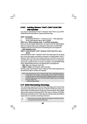
...RAID Installation Guide STEP 3: Install Windows® VistaTM / Windows® VistaTM 64-bit OS on SATA / SATAII HDDs, you still need to [CPU, PCIE, Async.]. Enter BIOS SETUP UTILITY Advanced screen IDE Configuration. Set the "SATA Operation Mode" option to load the NVIDIA® RAID drivers.... page, please insert the ASRock Support CD into the optical drive to boot your system, and follow below steps. STEP 2: Use "RAID Installation Guide" to install ...
...RAID Installation Guide STEP 3: Install Windows® VistaTM / Windows® VistaTM 64-bit OS on SATA / SATAII HDDs, you still need to [CPU, PCIE, Async.]. Enter BIOS SETUP UTILITY Advanced screen IDE Configuration. Set the "SATA Operation Mode" option to load the NVIDIA® RAID drivers.... page, please insert the ASRock Support CD into the optical drive to boot your system, and follow below steps. STEP 2: Use "RAID Installation Guide" to install ...
User Manual
Page 34
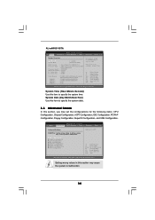
...section, you may set the configurations for the following items: CPU Configuration, Chipset Configuration, ACPI Configuration, IDE Configuration, PCIPnP Configuration, Floppy Configuration, SuperIO Configuration, and USB Configuration. CPU Configuration Chipset Configuration ACPI Configuration IDE Configuration PCIPnP Configuration Floppy Configuration...Help F9 Load Defaults F10 Save and Exit ESC Exit v02.54 (C) Copyright 1985-2003, American Megatrends, Inc. ALiveNF6G-VSTA BIOS SETUP UTILITY Main Advanced H/W Monitor Boot Security Exit System Overview System Time System Date [17:00:09]...
...section, you may set the configurations for the following items: CPU Configuration, Chipset Configuration, ACPI Configuration, IDE Configuration, PCIPnP Configuration, Floppy Configuration, SuperIO Configuration, and USB Configuration. CPU Configuration Chipset Configuration ACPI Configuration IDE Configuration PCIPnP Configuration Floppy Configuration...Help F9 Load Defaults F10 Save and Exit ESC Exit v02.54 (C) Copyright 1985-2003, American Megatrends, Inc. ALiveNF6G-VSTA BIOS SETUP UTILITY Main Advanced H/W Monitor Boot Security Exit System Overview System Time System Date [17:00:09]...
User Manual
Page 35
...200]. The default value is [Disabled]. PCIE Frequency (MHz) Use this option to [Enabled], you set to [Enabled] as default. CPU/LDT Spread Spectrum This feature will be set to select Overclock Mode. Configuration options: [Disabled], and [Enabled]. 35 Configuration options: [...Disabled], and [Enabled]. AM2 Boost If you will enable ASRock AM2 Boost function, which will be set based on page 8 for details. The default value is [Auto]. If Manual, multiplier...
...200]. The default value is [Disabled]. PCIE Frequency (MHz) Use this option to [Enabled], you set to [Enabled] as default. CPU/LDT Spread Spectrum This feature will be set to select Overclock Mode. Configuration options: [Disabled], and [Enabled]. 35 Configuration options: [...Disabled], and [Enabled]. AM2 Boost If you will enable ASRock AM2 Boost function, which will be set based on page 8 for details. The default value is [Auto]. If Manual, multiplier...
User Manual
Page 36
.... Processor Maximum Multiplier It will display Processor Maximum Voltage for system stability. However, it is set based on the CPU you use Dual Core CPU. The default value is recommended to [Enabled]. Configuration optiona: [Enabled], [Disabled]. Processor Multiplier This item will be...this item to [Auto] by default. However, for reference. Configuration options: [Auto], [Enabled] and [Disabled]. If you may reduce CPU voltage and memory frequency, and lead to enable or disable AMD's Cool 'n' QuietTM technology. Please note that enabling this function may adjust...
.... Processor Maximum Multiplier It will display Processor Maximum Voltage for system stability. However, it is set based on the CPU you use Dual Core CPU. The default value is recommended to [Enabled]. Configuration optiona: [Enabled], [Disabled]. Processor Multiplier This item will be...this item to [Auto] by default. However, for reference. Configuration options: [Auto], [Enabled] and [Disabled]. If you may reduce CPU voltage and memory frequency, and lead to enable or disable AMD's Cool 'n' QuietTM technology. Please note that enabling this function may adjust...
User Manual
Page 37
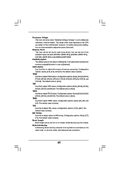
... to adjust the value of this motherboard. Flexibility Option The default value of this item to adjust the means of the value depends on the CPU you adopt on the same node, or accross nodes, decreasing access contention. 37 The default value is [Auto]. Processor Voltage This item will allow better...
... to adjust the value of this motherboard. Flexibility Option The default value of this item to adjust the means of the value depends on the CPU you adopt on the same node, or accross nodes, decreasing access contention. 37 The default value is [Auto]. Processor Voltage This item will allow better...

User Manual
Page 38
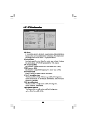
...Advanced Chipset Settings Onboard LAN Onboard HD Audio Front Panel Controller Share Memory Primary Graphics Adapter [Enabled] [Auto] [Auto] [Auto] [PCI] CPU-NB Link Speed CPU-NB Kink Width DRAM Voltage [Auto] [Auto] [Auto] To set share memory feature. The default value of multiple video controllers. NB ...Link Speed This feature allows you selecting CPU to NB link width. NB Link Width This feature allows you selecting CPU to enable or disable memory hole. OnBoard LAN This allows you to select the type of Primary...
...Advanced Chipset Settings Onboard LAN Onboard HD Audio Front Panel Controller Share Memory Primary Graphics Adapter [Enabled] [Auto] [Auto] [Auto] [PCI] CPU-NB Link Speed CPU-NB Kink Width DRAM Voltage [Auto] [Auto] [Auto] To set share memory feature. The default value of multiple video controllers. NB ...Link Speed This feature allows you selecting CPU to NB link width. NB Link Width This feature allows you selecting CPU to enable or disable memory hole. OnBoard LAN This allows you to select the type of Primary...

User Manual
Page 45
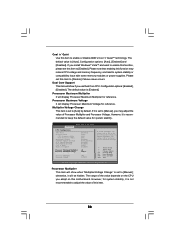
...section, it allows you to monitor the status of the hardware on your system, including the parameters of the CPU temperature, motherboard temperature, CPU fan speed, chassis fan speed, and the critical voltage. You are allowed to enable this item to enable.... BIOS SETUP UTILITY Main Advanced H/W Monitor Boot Security Exit Hardware Health Event Monitoring CPU Ambient Temperature CPU Internal Temperature M / B Temperature CPU Fan Speed Chassis Fan Speed Vcore + 3.30V + 5.00V + 12.00V CPU Quiet Fan : 42 C / 107 F : 52 C / 125 F : 31 C / 87 F : 2833 RPM : N/A : 1.532 V : 3.129 V : 4.877 V :...
...section, it allows you to monitor the status of the hardware on your system, including the parameters of the CPU temperature, motherboard temperature, CPU fan speed, chassis fan speed, and the critical voltage. You are allowed to enable this item to enable.... BIOS SETUP UTILITY Main Advanced H/W Monitor Boot Security Exit Hardware Health Event Monitoring CPU Ambient Temperature CPU Internal Temperature M / B Temperature CPU Fan Speed Chassis Fan Speed Vcore + 3.30V + 5.00V + 12.00V CPU Quiet Fan : 42 C / 107 F : 52 C / 125 F : 31 C / 87 F : 2833 RPM : N/A : 1.532 V : 3.129 V : 4.877 V :...

Quick Installation Guide
Page 2
... (PCIE1) 32 ATX Power Connector (ATXPWR1) 33 Serial Port Connector (COM1) 2 ASRock ALiveNF6G-DVI / ALiveNF6G-VSTA Motherboard Yellow) 7 2 x 240-pin DDRII DIMM Slots (Dual Channel B: DDRII_3, DDRII_4; Motherboard Layout (ALiveNF6G-DVI) English 1 PS2_USB_PW1 Jumper 2 ATX 12V Power Connector (ATX12V1) 3 CPU Heatsink Retention Module 4 AM2 940-Pin CPU Socket 5 CPU Fan Connector (CPU_FAN1) 6 2 x 240-pin DDRII DIMM Slots (Dual Channel...
... (PCIE1) 32 ATX Power Connector (ATXPWR1) 33 Serial Port Connector (COM1) 2 ASRock ALiveNF6G-DVI / ALiveNF6G-VSTA Motherboard Yellow) 7 2 x 240-pin DDRII DIMM Slots (Dual Channel B: DDRII_3, DDRII_4; Motherboard Layout (ALiveNF6G-DVI) English 1 PS2_USB_PW1 Jumper 2 ATX 12V Power Connector (ATX12V1) 3 CPU Heatsink Retention Module 4 AM2 940-Pin CPU Socket 5 CPU Fan Connector (CPU_FAN1) 6 2 x 240-pin DDRII DIMM Slots (Dual Channel...
Quick Installation Guide
Page 3
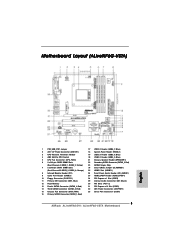
Motherboard Layout (ALiveNF6G-VSTA) English 1 PS2_USB_PW1 Jumper 2 ATX 12V Power Connector (ATX12V1) 3 CPU Heatsink Retention Module 4 AM2 940-Pin CPU Socket 5 CPU Fan Connector (CPU_FAN1) 6 2 x 240-pin DDRII DIMM Slots (Dual Channel A: DDRII_1, DDRII_2; Orange) 8 Infrared Module Header (IR1) 9 Game Port Header (GAME1) 10 Floppy ...: CD1 (Black) 30 PCI Slots (PCI1- 2) 31 PCI Express x16 Slot (PCIE1) 32 ATX Power Connector (ATXPWR1) 33 Serial Port Connector (COM1) 3 ASRock ALiveNF6G-DVI / ALiveNF6G-VSTA Motherboard Yellow) 7 2 x 240-pin DDRII DIMM Slots (Dual Channel B: DDRII_3, DDRII_4;
Motherboard Layout (ALiveNF6G-VSTA) English 1 PS2_USB_PW1 Jumper 2 ATX 12V Power Connector (ATX12V1) 3 CPU Heatsink Retention Module 4 AM2 940-Pin CPU Socket 5 CPU Fan Connector (CPU_FAN1) 6 2 x 240-pin DDRII DIMM Slots (Dual Channel A: DDRII_1, DDRII_2; Orange) 8 Infrared Module Header (IR1) 9 Game Port Header (GAME1) 10 Floppy ...: CD1 (Black) 30 PCI Slots (PCI1- 2) 31 PCI Express x16 Slot (PCIE1) 32 ATX Power Connector (ATXPWR1) 33 Serial Port Connector (COM1) 3 ASRock ALiveNF6G-DVI / ALiveNF6G-VSTA Motherboard Yellow) 7 2 x 240-pin DDRII DIMM Slots (Dual Channel B: DDRII_3, DDRII_4;


