RAID Installation Guide
Page 2
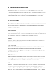
... added together. However, in our support CD or "Quick Installation Guide", then you to configure RAID functions by following the detailed instruction of the "User Manual" in RAIDXpert, 2 It will improve data access and storage since the disk array management software will direct all applications to the next drive automatically. Hot...
... added together. However, in our support CD or "Quick Installation Guide", then you to configure RAID functions by following the detailed instruction of the "User Manual" in RAIDXpert, 2 It will improve data access and storage since the disk array management software will direct all applications to the next drive automatically. Hot...
RAID Installation Guide
Page 8
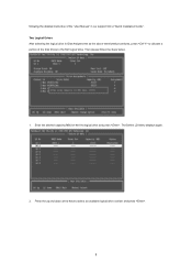
Press the up and down arrow keys to the first logical drive. The Define LD Menu displays again. 2. Enter the desired capacity (MB) for the first logical drive and press . Then please follow the steps below. 1. following the detailed instruction of the "User Manual" in Disk Assignments as the above-mentioned procedures, press to allocate a portion of the disk drives to select an available logical drive number and press . 8 Two Logical Drives After selecting the logical drive in our support CD or "Quick Installation Guide".
Press the up and down arrow keys to the first logical drive. The Define LD Menu displays again. 2. Enter the desired capacity (MB) for the first logical drive and press . Then please follow the steps below. 1. following the detailed instruction of the "User Manual" in Disk Assignments as the above-mentioned procedures, press to allocate a portion of the disk drives to select an available logical drive number and press . 8 Two Logical Drives After selecting the logical drive in our support CD or "Quick Installation Guide".
RAID Installation Guide
Page 9
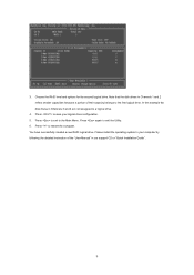
Press again to the first logical drive. Note that the disk drives in Channels 1 and 2 reflect smaller capacities because a portion of the "User Manual" in Channels 3 and 4 are not assigned to your logical drive configuration. 5. 3. Choose the RAID level and options for the second logical drive. Press to restart ...
Press again to the first logical drive. Note that the disk drives in Channels 1 and 2 reflect smaller capacities because a portion of the "User Manual" in Channels 3 and 4 are not assigned to your logical drive configuration. 5. 3. Choose the RAID level and options for the second logical drive. Press to restart ...
RAID Installation Guide
Page 13
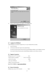
Or, log on manually with your entry looks like this: http://127.0.0.1:25902/ati or http://localhost:25902/ati 2.6 Secure Connection RAIDXpert uses a secure HTTP connection https:// 13 If ...
Or, log on manually with your entry looks like this: http://127.0.0.1:25902/ati or http://localhost:25902/ati 2.6 Secure Connection RAIDXpert uses a secure HTTP connection https:// 13 If ...

User Manual
Page 1
All rights reserved. 1 A785GMH/128M User Manual Version 1.0 Published August 2009 Copyright©2009 ASRock INC.
All rights reserved. 1 A785GMH/128M User Manual Version 1.0 Published August 2009 Copyright©2009 ASRock INC.

User Manual
Page 2
...be constructed as a commitment by ASRock. With respect to the contents of this manual, ASRock does not provide warranty of any kind, either expressed or implied, including but not limited to the owners' benefit, without written consent of ASRock Inc. "Perchlorate Material-special handling...particular purpose. Products and corporate names appearing in this manual may or may apply, see www.dtsc.ca.gov/hazardouswaste/perchlorate" ASRock Website: http://www.asrock.com 2 Disclaimer: Specifications and information contained in this manual are used only for informational use only and subject ...
...be constructed as a commitment by ASRock. With respect to the contents of this manual, ASRock does not provide warranty of any kind, either expressed or implied, including but not limited to the owners' benefit, without written consent of ASRock Inc. "Perchlorate Material-special handling...particular purpose. Products and corporate names appearing in this manual may or may apply, see www.dtsc.ca.gov/hazardouswaste/perchlorate" ASRock Website: http://www.asrock.com 2 Disclaimer: Specifications and information contained in this manual are used only for informational use only and subject ...

User Manual
Page 5
...-by-step guide to this motherboard, please visit our website for purchasing ASRock A785GMH/128M motherboard, a reliable motherboard produced under ASRock's consistently stringent quality control. In this manual, chapter 1 and 2 contain introduction of this manual will be available on ASRock website as well. ASRock website http://www.asrock.com If you are using. It delivers excellent performance with robust...
...-by-step guide to this motherboard, please visit our website for purchasing ASRock A785GMH/128M motherboard, a reliable motherboard produced under ASRock's consistently stringent quality control. In this manual, chapter 1 and 2 contain introduction of this manual will be available on ASRock website as well. ASRock website http://www.asrock.com If you are using. It delivers excellent performance with robust...

User Manual
Page 17
... install the CPU into this motherboard, it firmly on the side tab to secure the CPU. For proper installation, please kindly refer to the instruction manuals of CPU Fan and Heatsink After you push down the socket lever to indicate that the CPU corner with the golden triangle matches the socket...
... install the CPU into this motherboard, it firmly on the side tab to secure the CPU. For proper installation, please kindly refer to the instruction manuals of CPU Fan and Heatsink After you push down the socket lever to indicate that the CPU corner with the golden triangle matches the socket...

User Manual
Page 29
... Settings, and then select Chipset Configuration. Set the Front Panel Control option from [Auto] to install your system. 2. Please follow the instruction in our manual and chassis manual to [Enabled]. Connect Ground (GND) to MIC2_L. D. Please connect the chassis speaker to this connector and match the black wire to the front panel...
... Settings, and then select Chipset Configuration. Set the Front Panel Control option from [Auto] to install your system. 2. Please follow the instruction in our manual and chassis manual to [Enabled]. Connect Ground (GND) to MIC2_L. D. Please connect the chassis speaker to this connector and match the black wire to the front panel...

User Manual
Page 33
... interfaces, the IDE 1x4-pin conventional power connector interface is designed only for SATA / SATAII HDD in the product spec on our support website: www.asrock.com 4. Please read below instructions step by the chipset because of its limitation, the SATA / SATAII Hot Plug support information of our motherboard is indicated... cable with SATA 15-pin power connector interface A. Make sure your SATA / SATAII HDD can support Hot Plug function from your dealer or HDD user manual. The SATA / SATAII HDD, which cannot support Hot Plug function, will cause the HDD damage and data loss.
... interfaces, the IDE 1x4-pin conventional power connector interface is designed only for SATA / SATAII HDD in the product spec on our support website: www.asrock.com 4. Please read below instructions step by the chipset because of its limitation, the SATA / SATAII Hot Plug support information of our motherboard is indicated... cable with SATA 15-pin power connector interface A. Make sure your SATA / SATAII HDD can support Hot Plug function from your dealer or HDD user manual. The SATA / SATAII HDD, which cannot support Hot Plug function, will cause the HDD damage and data loss.

User Manual
Page 43
...Auto] [Disabled] Processor Maximum Frequency x10.5 2100 MHZ North Bridge Maximum Frequency x9.0 1800 MHz Processor Maximum Voltage 1.2500 V Multiplier/Voltage Change [Manual] CPU Frequency Multiplier [x0.5 100 MHz] CPU Voltage [0.6000 V] NB Frequency Multiplier [x5.0 1000 MHz] Overclocking may adjust the value of the... you select [Per Core], you adopt on the CPU you will show when "Multiplier/Voltage Change" is not recommended to [Manual]; The range of Processor Frequency and Processor Voltage. However, for system stability, it is set to adjust the value of the...
...Auto] [Disabled] Processor Maximum Frequency x10.5 2100 MHZ North Bridge Maximum Frequency x9.0 1800 MHz Processor Maximum Voltage 1.2500 V Multiplier/Voltage Change [Manual] CPU Frequency Multiplier [x0.5 100 MHz] CPU Voltage [0.6000 V] NB Frequency Multiplier [x5.0 1000 MHz] Overclocking may adjust the value of the... you select [Per Core], you adopt on the CPU you will show when "Multiplier/Voltage Change" is not recommended to [Manual]; The range of Processor Frequency and Processor Voltage. However, for system stability, it is set to adjust the value of the...

Quick Installation Guide
Page 5
.../support/index.asp 1.1 Package Contents 1 x ASRock A785GMH/128M Motherboard (Micro ATX Form Factor: 9.6-in x 8.6-in, 24.4 cm x 21.8 cm) 1 x ASRock A785GMH/128M Quick Installation Guide 2 x ASRock A785GMH/128M Support CD 1 x Ultra ATA 66/100/133 IDE Ribbon Cable (80-conductor) 2 x Serial ATA (SATA) Data Cables (Optional) 1 x I/O Panel Shield 5 ASRock A785GMH/128M Motherboard English In this manual occur, the updated version will be available...
.../support/index.asp 1.1 Package Contents 1 x ASRock A785GMH/128M Motherboard (Micro ATX Form Factor: 9.6-in x 8.6-in, 24.4 cm x 21.8 cm) 1 x ASRock A785GMH/128M Quick Installation Guide 2 x ASRock A785GMH/128M Support CD 1 x Ultra ATA 66/100/133 IDE Ribbon Cable (80-conductor) 2 x Serial ATA (SATA) Data Cables (Optional) 1 x I/O Panel Shield 5 ASRock A785GMH/128M Motherboard English In this manual occur, the updated version will be available...

Quick Installation Guide
Page 9
...4-channel, 6-channel, and 8-channel modes. Please check the table on the same motherboard. 9 ASRock A785GMH/128M Motherboard English It is a user-friendly ASRock overclocking tool which allows you to surveil your system by ASRock, provides a convenient way for the operation procedures of Intelligent Energy Saver. The voltage regulator can ...asrock.com 11. To use FAT32/16/12 file system. 13. Just launch this utility, you can reduce the number of output phases to improve efficiency when the CPU cores are idle. 6. 1080p Blu-ray (BD) / HD-DVD playback support on page 31 of "User Manual...
...4-channel, 6-channel, and 8-channel modes. Please check the table on the same motherboard. 9 ASRock A785GMH/128M Motherboard English It is a user-friendly ASRock overclocking tool which allows you to surveil your system by ASRock, provides a convenient way for the operation procedures of Intelligent Energy Saver. The voltage regulator can ...asrock.com 11. To use FAT32/16/12 file system. 13. Just launch this utility, you can reduce the number of output phases to improve efficiency when the CPU cores are idle. 6. 1080p Blu-ray (BD) / HD-DVD playback support on page 31 of "User Manual...

Quick Installation Guide
Page 14
... fan to dissipate heat. The lever clicks on the socket while you install the CPU into this motherboard, it is in place. English 14 ASRock A785GMH/128M Motherboard Then connect the CPU fan to improve heat dissipation. Step 3. Lever 90° Up STEP 1: Lift Up The Socket Lever CPU Golden...The Socket Corner Small The Socket Lever Triangle 2.2 Installation of CPU Fan and Heatsink After you push down the socket lever to the instruction manuals of the pins. For proper installation, please kindly refer to secure the CPU. Position the CPU directly above the socket such that the ...
... fan to dissipate heat. The lever clicks on the socket while you install the CPU into this motherboard, it is in place. English 14 ASRock A785GMH/128M Motherboard Then connect the CPU fan to improve heat dissipation. Step 3. Lever 90° Up STEP 1: Lift Up The Socket Lever CPU Golden...The Socket Corner Small The Socket Lever Triangle 2.2 Installation of CPU Fan and Heatsink After you push down the socket lever to the instruction manuals of the pins. For proper installation, please kindly refer to secure the CPU. Position the CPU directly above the socket such that the ...

Quick Installation Guide
Page 26
... fan cables to the fan connectors and match the black wire to this motherboard, please connect it to OUT2_L. Pin 1-3 Connected 3-Pin Fan Installation 26 ASRock A785GMH/128M Motherboard English Enter Advanced Settings, and then select Chipset Configuration. Though this connector and 3 2 match the black wire to install your system. 2. If ... Enter BIOS Setup Utility. Connect Mic_IN (MIC) to [Enabled]. B. D. Set the Front Panel Control option from [Auto] to MIC2_L. Please follow the instruction in our manual and chassis manual to the 1 ground pin.
... fan cables to the fan connectors and match the black wire to this motherboard, please connect it to OUT2_L. Pin 1-3 Connected 3-Pin Fan Installation 26 ASRock A785GMH/128M Motherboard English Enter Advanced Settings, and then select Chipset Configuration. Though this connector and 3 2 match the black wire to install your system. 2. If ... Enter BIOS Setup Utility. Connect Mic_IN (MIC) to [Enabled]. B. D. Set the Front Panel Control option from [Auto] to MIC2_L. Please follow the instruction in our manual and chassis manual to the 1 ground pin.

Quick Installation Guide
Page 30
..., which allows you wish to the User Manual (PDF file) contained in your CD-ROM drive. otherwise, POST continues with the motherboard contains necessary drivers and useful utilities that will display the Main Menu automatically if "AUTORUN" is designed to display the menus. 30 ASRock A785GMH/128M Motherboard English To begin using the Support...
..., which allows you wish to the User Manual (PDF file) contained in your CD-ROM drive. otherwise, POST continues with the motherboard contains necessary drivers and useful utilities that will display the Main Menu automatically if "AUTORUN" is designed to display the menus. 30 ASRock A785GMH/128M Motherboard English To begin using the Support...
