
User Manual
Page 11
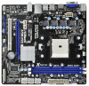
...USB5 USB 2.0 T: USB0 B: USB1 LAN AUDIO CODEC RJ-45 LAN RoHS Dual Graphics ErP/EuP Ready SATA3 6Gb/s USB 3.0 PWR_FAN1 32Mb BIOS PCIE1 A75M-HVS PCIE2 AMD A75 FCH (Hudson-D3) Chipset PCI1 CMOS BATTERY XFast USB Super I/O Designed in Taipei HD_AUDIO1 1 USB10_11 1 USB8_9 1 USB6_7 ...1 1 CIR1 IR1 1 CHA_FAN1 CLRCMOS1 PANEL 1 PLED PWRBTN 1 1 HDLED RESET COM1 1 1 LPT1 SATA_1 SATA_3 SATA_5 1 SPEAKER1 SATA_2 SATA_4 SATA_6 6 7...
...USB5 USB 2.0 T: USB0 B: USB1 LAN AUDIO CODEC RJ-45 LAN RoHS Dual Graphics ErP/EuP Ready SATA3 6Gb/s USB 3.0 PWR_FAN1 32Mb BIOS PCIE1 A75M-HVS PCIE2 AMD A75 FCH (Hudson-D3) Chipset PCI1 CMOS BATTERY XFast USB Super I/O Designed in Taipei HD_AUDIO1 1 USB10_11 1 USB8_9 1 USB6_7 ...1 1 CIR1 IR1 1 CHA_FAN1 CLRCMOS1 PANEL 1 PLED PWRBTN 1 1 HDLED RESET COM1 1 1 LPT1 SATA_1 SATA_3 SATA_5 1 SPEAKER1 SATA_2 SATA_4 SATA_6 6 7...

User Manual
Page 23
To clear and reset the system parameters to short pin2 and pin3 on pins, the jumper is "Short". Please be noted ...11, No. 18) Setting Default Clear CMOS Description Note: CLRCMOS1 allows you do not clear the CMOS right after you update the BIOS. If no jumper cap is placed on pins, the jumper is removed. 23 The illustration shows a 3-pin jumper whose pin1 and ...pin2 are setup. If you need to clear the CMOS when you just nish updating the BIOS, you must boot up the system rst, and then shut it down before you to clear the data in CMOS. After ...
To clear and reset the system parameters to short pin2 and pin3 on pins, the jumper is "Short". Please be noted ...11, No. 18) Setting Default Clear CMOS Description Note: CLRCMOS1 allows you do not clear the CMOS right after you update the BIOS. If no jumper cap is placed on pins, the jumper is removed. 23 The illustration shows a 3-pin jumper whose pin1 and ...pin2 are setup. If you need to clear the CMOS when you just nish updating the BIOS, you must boot up the system rst, and then shut it down before you to clear the data in CMOS. After ...

Quick Installation Guide
Page 2
... 30 Power Fan Connector (PWR_FAN1) 15 Print Port Header (LPT1, White) English 2 ASRock A75M-HVS Motherboard Blue) 21 USB 2.0 Header (USB6_7, Blue) 6 ATX Power Connector (ATXPWR1)...RJ-45 LAN RoHS Dual Graphics ErP/EuP Ready SATA3 6Gb/s USB 3.0 PWR_FAN1 32Mb BIOS PCIE1 A75M-HVS PCIE2 AMD A75 FCH (Hudson-D3) Chipset PCI1 CMOS BATTERY XFast USB Super I/O ...Designed in Taipei HD_AUDIO1 1 USB10_11 1 USB8_9 1 USB6_7 1 1 CIR1 IR1 1 CHA_FAN1 CLRCMOS1 PANEL 1 PLED PWRBTN 1 1 HDLED RESET...
... 30 Power Fan Connector (PWR_FAN1) 15 Print Port Header (LPT1, White) English 2 ASRock A75M-HVS Motherboard Blue) 21 USB 2.0 Header (USB6_7, Blue) 6 ATX Power Connector (ATXPWR1)...RJ-45 LAN RoHS Dual Graphics ErP/EuP Ready SATA3 6Gb/s USB 3.0 PWR_FAN1 32Mb BIOS PCIE1 A75M-HVS PCIE2 AMD A75 FCH (Hudson-D3) Chipset PCI1 CMOS BATTERY XFast USB Super I/O ...Designed in Taipei HD_AUDIO1 1 USB10_11 1 USB8_9 1 USB6_7 1 1 CIR1 IR1 1 CHA_FAN1 CLRCMOS1 PANEL 1 PLED PWRBTN 1 1 HDLED RESET...

Quick Installation Guide
Page 20
... (CLRCMOS1) (see p.2, No. 18) Setting Default Clear CMOS Description Note: CLRCMOS1 allows you update the BIOS. If you need to clear the CMOS when you just finish updating the BIOS, you must boot up the system first, and then shut it down before you do not clear... placed on CLRCMOS1 for 5 seconds. The illustration shows a 3-pin jumper whose pin1 and pin2 are setup. English 20 ASRock A75M-HVS Motherboard When the jumper cap is "Open". To clear and reset the system parameters to short pin2 and pin3 on pins, the jumper is placed on these 2 pins. However, please ...
... (CLRCMOS1) (see p.2, No. 18) Setting Default Clear CMOS Description Note: CLRCMOS1 allows you update the BIOS. If you need to clear the CMOS when you just finish updating the BIOS, you must boot up the system first, and then shut it down before you do not clear... placed on CLRCMOS1 for 5 seconds. The illustration shows a 3-pin jumper whose pin1 and pin2 are setup. English 20 ASRock A75M-HVS Motherboard When the jumper cap is "Open". To clear and reset the system parameters to short pin2 and pin3 on pins, the jumper is placed on these 2 pins. However, please ...

Quick Installation Guide
Page 27
...contained in the Support CD to enter BIOS Setup after POST, please restart the system by pressing + + , or pressing the reset button on the motherboard stores BIOS Setup Utility. For the detailed information about BIOS Setup, please refer to enter BIOS Setup utility; 3. To begin using ... BIOS Information The Flash Memory on the system chassis. otherwise, POST continues with the motherboard contains necessary drivers and useful utilities that came with its various sub-menus and to be user-friendly. When you wish to display the menus. 27 ASRock A75M-HVS Motherboard...
...contained in the Support CD to enter BIOS Setup after POST, please restart the system by pressing + + , or pressing the reset button on the motherboard stores BIOS Setup Utility. For the detailed information about BIOS Setup, please refer to enter BIOS Setup utility; 3. To begin using ... BIOS Information The Flash Memory on the system chassis. otherwise, POST continues with the motherboard contains necessary drivers and useful utilities that came with its various sub-menus and to be user-friendly. When you wish to display the menus. 27 ASRock A75M-HVS Motherboard...


