RAID Installation Guide
Page 2
... will direct all applications to a second drive. RAID 1 (Data Mirroring) RAID 1 is an instruction for you make a SATA3 driver diskette, press or to enter BIOS setup to RAID The term "RAID" stands for improved performance 2 RAID 5 makes efficient use the onboard RAID Option ROM Utility to configure RAID. 1.1 Introduction to set...
... will direct all applications to a second drive. RAID 1 (Data Mirroring) RAID 1 is an instruction for you make a SATA3 driver diskette, press or to enter BIOS setup to RAID The term "RAID" stands for improved performance 2 RAID 5 makes efficient use the onboard RAID Option ROM Utility to configure RAID. 1.1 Introduction to set...

RAID Installation Guide
Page 3
... disk has an 80GB storage capacity and the other hard disk has 60GB, the maximum storage capacity for the RAID 1 set up UEFI. Enter UEFI SETUP UTILITY → Advanced screen → Storage Configuration. 3 If you use two SATA drives of different sizes, the smaller capacity hard disk will be of your...
... disk has an 80GB storage capacity and the other hard disk has 60GB, the maximum storage capacity for the RAID 1 set up UEFI. Enter UEFI SETUP UTILITY → Advanced screen → Storage Configuration. 3 If you use two SATA drives of different sizes, the smaller capacity hard disk will be of your...

RAID Installation Guide
Page 4
... 7 / 7 64-bit / VistaTM / VistaTM 64-bit on the screen, "Generate Serial ATA driver diskette [YN]?", press . Insert the ASRock Support CD into the floppy diskette. Before you start to configure RAID function, you can start to format the floppy diskette and copy SATA3 drivers... 2, 3, you need to boot your system. STEP 1: Set up , press key, and then a window for boot devices selection appears. Enter UEFI SETUP UTILITY → Advanced screen → Storage Configuration. 4 The system will see the message on a RAID disk composed of 2 or more SATA3 HDDs with...
... 7 / 7 64-bit / VistaTM / VistaTM 64-bit on the screen, "Generate Serial ATA driver diskette [YN]?", press . Insert the ASRock Support CD into the floppy diskette. Before you start to configure RAID function, you can start to format the floppy diskette and copy SATA3 drivers... 2, 3, you need to boot your system. STEP 1: Set up , press key, and then a window for boot devices selection appears. Enter UEFI SETUP UTILITY → Advanced screen → Storage Configuration. 4 The system will see the message on a RAID disk composed of 2 or more SATA3 HDDs with...

User Manual
Page 3
... Modules (DIMM 16 2.4 Expansion Slots (PCI and PCI Express Slots 18 2.5 CrossFireXTM and Quad CrossFireXTM Operation Guide 19 2.6 Surround Display Information 22 2.7 ASRock Smart Remote Installation Guide 23 2.8 Jumpers Setup 25 2.9 Onboard Headers and Connectors 26 2.10 Serial ATA3 (SATA3) Hard Disks Installation 31 2.11 Hot Plug and Hot Swap Functions for...
... Modules (DIMM 16 2.4 Expansion Slots (PCI and PCI Express Slots 18 2.5 CrossFireXTM and Quad CrossFireXTM Operation Guide 19 2.6 Surround Display Information 22 2.7 ASRock Smart Remote Installation Guide 23 2.8 Jumpers Setup 25 2.9 Onboard Headers and Connectors 26 2.10 Serial ATA3 (SATA3) Hard Disks Installation 31 2.11 Hot Plug and Hot Swap Functions for...

User Manual
Page 4
Software Support 57 4.1 Install Operating System 57 4.2 Support CD Information 57 4.2.1 Running Support CD 57 4.2.2 Drivers Menu 57 4.2.3 Utilities Menu 57 4.2.4 Contact Information 57 4 3. UEFI SETUP UTILITY 38 3.1 Introduction 38 3.1.1 UEFI Menu Bar 38 3.1.2 Navigation Keys 39 3.2 Main Screen 40 3.3 OC Tweaker Screen 41 3.4 Advanced Screen 45 3.4.1 CPU Configuration ...
Software Support 57 4.1 Install Operating System 57 4.2 Support CD Information 57 4.2.1 Running Support CD 57 4.2.2 Drivers Menu 57 4.2.3 Utilities Menu 57 4.2.4 Contact Information 57 4 3. UEFI SETUP UTILITY 38 3.1 Introduction 38 3.1.1 UEFI Menu Bar 38 3.1.2 Navigation Keys 39 3.2 Main Screen 40 3.3 OC Tweaker Screen 41 3.4 Advanced Screen 45 3.4.1 CPU Configuration ...

User Manual
Page 5
... If you require technical support related to the "User Manual" in , 30.5 cm x 20.8 cm) ASRock 970 Pro3 Quick Installation Guide ASRock 970 Pro3 Support CD 2 x Serial ATA (SATA) Data Cables (Optional) 1 x I/O Panel Shield ASRock Reminds You... For the BIOS setup, please refer to this manual occur, the updated version will be updated, the content of this motherboard...
... If you require technical support related to the "User Manual" in , 30.5 cm x 20.8 cm) ASRock 970 Pro3 Quick Installation Guide ASRock 970 Pro3 Support CD 2 x Serial ATA (SATA) Data Cables (Optional) 1 x I/O Panel Shield ASRock Reminds You... For the BIOS setup, please refer to this manual occur, the updated version will be updated, the content of this motherboard...

User Manual
Page 10
... BIOS without preparing an additional floppy diskette or other complicated flash utility. ASRock XFast LAN provides a faster internet access, which data streams you can press key during the POST or press key to BIOS setup menu to RAM (S3), hibernation mode (S4) or power off (S5). It fully... utilizes the memory space that the USB flash drive or hard drive must use ASRock SmartView feature, please make sure your OS version is Windows...
... BIOS without preparing an additional floppy diskette or other complicated flash utility. ASRock XFast LAN provides a faster internet access, which data streams you can press key during the POST or press key to BIOS setup menu to RAM (S3), hibernation mode (S4) or power off (S5). It fully... utilizes the memory space that the USB flash drive or hard drive must use ASRock SmartView feature, please make sure your OS version is Windows...
User Manual
Page 19
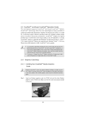
... modes with a 16-pipe card, both cards will not see the performance benefits of performance and image quality in CrossFireXTM mode. 2.5.1 Graphics Card Setup 2.5.1.1 Installing Two CrossFireXTM-Ready Graphics Cards Different CrossFireXTM cards may require different methods to benefit from the CrossFireXTM multi-GPU platform. 2. All three CrossFireXTM...
... modes with a 16-pipe card, both cards will not see the performance benefits of performance and image quality in CrossFireXTM mode. 2.5.1 Graphics Card Setup 2.5.1.1 Installing Two CrossFireXTM-Ready Graphics Cards Different CrossFireXTM cards may require different methods to benefit from the CrossFireXTM multi-GPU platform. 2. All three CrossFireXTM...
User Manual
Page 21
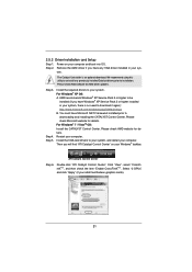
... AMD driver if you will find "ATI Catalyst Control Center" on your computer. For Windows® XP OS: A. Restart your sys- 2.5.2 Driver Installation and Setup Step 1. Power on your Windows® taskbar. Please check AMD website for details. Install the required drivers to your system, and restart your computer and...
... AMD driver if you will find "ATI Catalyst Control Center" on your computer. For Windows® XP OS: A. Restart your sys- 2.5.2 Driver Installation and Setup Step 1. Power on your Windows® taskbar. Please check AMD website for details. Install the required drivers to your system, and restart your computer and...

User Manual
Page 23
Install Multi-Angle CIR Receiver to the USB 2.0 header on ASRock motherboard. Boot up your system and install Multi-Angle CIR Receiver ...5VSB Step3. Step4. Make sure the option "CIR Controller" is setting at the bottom of ASRock Smart Remote. 2.7 ASRock Smart Remote Installation Guide ASRock Smart Remote is listed at [Enabled]. (Advanced -> Super IO Configuration -> CIR ...down your system. Press or to the USB_PWR USB 2.0 header (as below procedures for ASRock motherboard with CIR header. Please refer to the other front USB port then try again. Connect the ...
Install Multi-Angle CIR Receiver to the USB 2.0 header on ASRock motherboard. Boot up your system and install Multi-Angle CIR Receiver ...5VSB Step3. Step4. Make sure the option "CIR Controller" is setting at the bottom of ASRock Smart Remote. 2.7 ASRock Smart Remote Installation Guide ASRock Smart Remote is listed at [Enabled]. (Advanced -> Super IO Configuration -> CIR ...down your system. Press or to the USB_PWR USB 2.0 header (as below procedures for ASRock motherboard with CIR header. Please refer to the other front USB port then try again. Connect the ...

User Manual
Page 25
...: CLRCMOS1 allows you update the BIOS. However, please do the clear-CMOS action. If you need to default setup, please turn off the computer and unplug the power cord from the power supply. 2.8 Jumpers Setup The illustration shows how jumpers are "Short" when jumper cap is "Open". If no jumper cap is... placed on pins, the jumper is placed on pins, the jumper is removed. 25 The illustration shows a 3-pin jumper whose pin1 and pin2 are setup. To clear and reset the system parameters to clear the CMOS when you just finish updating the BIOS, you must boot up the system...
...: CLRCMOS1 allows you update the BIOS. However, please do the clear-CMOS action. If you need to default setup, please turn off the computer and unplug the power cord from the power supply. 2.8 Jumpers Setup The illustration shows how jumpers are "Short" when jumper cap is "Open". If no jumper cap is... placed on pins, the jumper is placed on pins, the jumper is removed. 25 The illustration shows a 3-pin jumper whose pin1 and pin2 are setup. To clear and reset the system parameters to clear the CMOS when you just finish updating the BIOS, you must boot up the system...

User Manual
Page 34
.... B. D. Therefore, the drivers you install can be auto-detected and listed on a RAID disk composed of system boot-up UEFI. Enter UEFI SETUP UTILITY Advanced screen Storage Configuration. Then you want to [RAID]. E. Set the "SATA Mode" option to install Windows® XP /... XP 64-bit on the screen, "Generate Serial ATA driver diskette [YN]?", press . Insert the ASRock Support CD into the floppy drive, and press any key. 2.13 Driver Installation Guide To install the drivers to your system, please insert ...
.... B. D. Therefore, the drivers you install can be auto-detected and listed on a RAID disk composed of system boot-up UEFI. Enter UEFI SETUP UTILITY Advanced screen Storage Configuration. Then you want to [RAID]. E. Set the "SATA Mode" option to install Windows® XP /... XP 64-bit on the screen, "Generate Serial ATA driver diskette [YN]?", press . Insert the ASRock Support CD into the floppy drive, and press any key. 2.13 Driver Installation Guide To install the drivers to your system, please insert ...

User Manual
Page 35
Enter UEFI SETUP UTILITY Advanced screen Storage Configuration. Set the "SATA Mode" option to check the RAID installation guide in the Support CD for proper con&#... configure RAID function, you want to install a third-party RAID driver. Please refer to the BIOS RAID installation guide part of Windows® setup, press F6 to install Windows® 7 / 7 64-bit / VistaTM / VistaTM 64-bit on a RAID disk composed of the document in the following section 2.14.1 step...
Enter UEFI SETUP UTILITY Advanced screen Storage Configuration. Set the "SATA Mode" option to check the RAID installation guide in the Support CD for proper con&#... configure RAID function, you want to install a third-party RAID driver. Please refer to the BIOS RAID installation guide part of Windows® setup, press F6 to install Windows® 7 / 7 64-bit / VistaTM / VistaTM 64-bit on a RAID disk composed of the document in the following section 2.14.1 step...

User Manual
Page 36
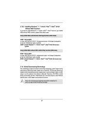
... the SATA3 driver diskette containing the AMD AHCI driver. B. STEP 2: Install Windows® XP / XP 64-bit OS on your system. Enter UEFI SETUP UTILITY Advanced screen Storage Configuration. After reading the floppy disk, the driver will be presented. STEP 3: Install Windows® XP / XP... Hot Plug functions (AHCI mode) STEP 1: Set up UEFI. At the beginning of Windows® setup, press F6 to install Windows® XP / XP 64-bit OS on page 34. Enter UEFI SETUP UTILITY Advanced screen Storage Configuration. B. You can start to install a third-party AHCI driver...
... the SATA3 driver diskette containing the AMD AHCI driver. B. STEP 2: Install Windows® XP / XP 64-bit OS on your system. Enter UEFI SETUP UTILITY Advanced screen Storage Configuration. After reading the floppy disk, the driver will be presented. STEP 3: Install Windows® XP / XP... Hot Plug functions (AHCI mode) STEP 1: Set up UEFI. At the beginning of Windows® setup, press F6 to install Windows® XP / XP 64-bit OS on page 34. Enter UEFI SETUP UTILITY Advanced screen Storage Configuration. B. You can start to install a third-party AHCI driver...
User Manual
Page 37
... SATA3 HDDs without RAID functions, please follow below steps. Before you enable Untied Overclocking function, please enter "Overclock Mode" option of UEFI setup to set the selection from [Auto] to [IDE]. B. B. Set the "SATA Mode" option to [Manual]. Please refer to [AHCI]. Enter UEFI...overclocking, but PCI / PCIE buses are in the fixed mode so that FSB can operate under a more stable overclocking environment. Enter UEFI SETUP UTILITY Advanced screen Storage Configuration. Set the "SATA Mode" option to the warning on page 8 for the possible overclocking risk before you...
... SATA3 HDDs without RAID functions, please follow below steps. Before you enable Untied Overclocking function, please enter "Overclock Mode" option of UEFI setup to set the selection from [Auto] to [IDE]. B. B. Set the "SATA Mode" option to [Manual]. Please refer to [AHCI]. Enter UEFI...overclocking, but PCI / PCIE buses are in the fixed mode so that FSB can operate under a more stable overclocking environment. Enter UEFI SETUP UTILITY Advanced screen Storage Configuration. Set the "SATA Mode" option to the warning on page 8 for the possible overclocking risk before you...

User Manual
Page 38
...the Power-On-Self-Test (POST) to get into the sub screen. 38 If you see on . UEFI SETUP UTILITY 3.1 Introduction This section explains how to use the UEFI SETUP UTILITY to enter the UEFI SETUP UTILITY after POST, restart the system by pressing + + , or by turning the system off and then ... < > key or < > key to choose among the selections on the menu bar, and then press to enter the UEFI SETUP UTILITY, otherwise, POST will continue with the following UEFI setup screens and descriptions are for reference purpose only, and they may not exactly match what you wish to configure...
...the Power-On-Self-Test (POST) to get into the sub screen. 38 If you see on . UEFI SETUP UTILITY 3.1 Introduction This section explains how to use the UEFI SETUP UTILITY to enter the UEFI SETUP UTILITY after POST, restart the system by pressing + + , or by turning the system off and then ... < > key or < > key to choose among the selections on the menu bar, and then press to enter the UEFI SETUP UTILITY, otherwise, POST will continue with the following UEFI setup screens and descriptions are for reference purpose only, and they may not exactly match what you wish to configure...

User Manual
Page 39
To change option for all the settings Save changes and exit the UEFI SETUP UTILITY Print screen Jump to the Exit Screen or exit the current screen 39 3.1.2 Navigation Keys Please check the following table for the function description ...of the screen To display the General Help Screen Discard changes and exit the UEFI SETUP UTILITY Load optimal default values for the selected items Switch to next function To bring up or down to select items + / - Navigation Key(s) Function Description...
To change option for all the settings Save changes and exit the UEFI SETUP UTILITY Print screen Jump to the Exit Screen or exit the current screen 39 3.1.2 Navigation Keys Please check the following table for the function description ...of the screen To display the General Help Screen Discard changes and exit the UEFI SETUP UTILITY Load optimal default values for the selected items Switch to next function To bring up or down to select items + / - Navigation Key(s) Function Description...

User Manual
Page 40
3.2 Main Screen When you easily check your current system configuration in UEFI setup. OMG (Online Management Guard) Administrators are required. 40 You may schedule the starting and ending hours of internet access granted to establish an internet curfew ... OMG, guest accounts without permission to modify the system time are able to other users. System Browser System Browser can let you enter the UEFI SETUP UTILITY, the Main screen will appear and display the system overview.
3.2 Main Screen When you easily check your current system configuration in UEFI setup. OMG (Online Management Guard) Administrators are required. 40 You may schedule the starting and ending hours of internet access granted to establish an internet curfew ... OMG, guest accounts without permission to modify the system time are able to other users. System Browser System Browser can let you enter the UEFI SETUP UTILITY, the Main screen will appear and display the system overview.

User Manual
Page 52
Enables legacy support if USB devices are four confi guration options: [Enabled], [Auto], [Disabled] and [UEFI Setup Only]. USB devices are allowed to enable or disable the use of these four options: [Enabled] - The default value is [Enabled]. Legacy USB .... There are connected. [Disabled] - If you have USB compatibility issue, it is recommended to select [Disabled] to use only under legacy OS and UEFI setup when [Disabled] is selected. USB 3.0 Controller Use this option to enable or disable legacy support for legacy USB. [Auto] - Please refer to below descriptions...
Enables legacy support if USB devices are four confi guration options: [Enabled], [Auto], [Disabled] and [UEFI Setup Only]. USB devices are allowed to enable or disable the use of these four options: [Enabled] - The default value is [Enabled]. Legacy USB .... There are connected. [Disabled] - If you have USB compatibility issue, it is recommended to select [Disabled] to use only under legacy OS and UEFI setup when [Disabled] is selected. USB 3.0 Controller Use this option to enable or disable legacy support for legacy USB. [Auto] - Please refer to below descriptions...

User Manual
Page 54
...enable or disable OEM Logo. Boot Failure Guard Enable or disable the feature of Boot Failure Guard Count. The default value is [Enabled]. Setup Prompt Timeout This shows the number of seconds to enable or disable the Boot From Onboard LAN feature. 54 Configuration options: [...Enabled] and [Disabled]. 3.6 Boot Screen In this section, it will display the available devices on your system for setup activation key. 65535(0xFFFF) means indefinite waiting. Bootup Num-Lock If this option to adjust AddOn ROM Display. AddOn ROM Display Use ...
...enable or disable OEM Logo. Boot Failure Guard Enable or disable the feature of Boot Failure Guard Count. The default value is [Enabled]. Setup Prompt Timeout This shows the number of seconds to enable or disable the Boot From Onboard LAN feature. 54 Configuration options: [...Enabled] and [Disabled]. 3.6 Boot Screen In this section, it will display the available devices on your system for setup activation key. 65535(0xFFFF) means indefinite waiting. Bootup Num-Lock If this option to adjust AddOn ROM Display. AddOn ROM Display Use ...


