User Manual
Page 2
... Perchlorate Best Management Practices (BMP) regulations passed by the California Legislature. CALIFORNIA, USA ONLY The Lithium battery adopted on this motherboard contains Perchlorate, a toxic substance controlled in this manual may or may not be registered trademarks or copyrights of their respective companies,... battery in California, USA, please follow the related regulations in any form or by any means, except duplication of documentation by ASRock. Copyright Notice: No part of this manual may be reproduced, transcribed, transmitted, or translated in any language, in advance. ...
... Perchlorate Best Management Practices (BMP) regulations passed by the California Legislature. CALIFORNIA, USA ONLY The Lithium battery adopted on this motherboard contains Perchlorate, a toxic substance controlled in this manual may or may not be registered trademarks or copyrights of their respective companies,... battery in California, USA, please follow the related regulations in any form or by any means, except duplication of documentation by ASRock. Copyright Notice: No part of this manual may be reproduced, transcribed, transmitted, or translated in any language, in advance. ...
User Manual
Page 3
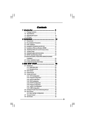
Contents 1 Introduction 5 1.1 Package Contents 5 1.2 Specifications 6 1.3 Motherboard Layout 10 1.4 I/O Panel 11 2 Installation 12 2.1 Screw Holes 12 2.2 Pre-installation Precautions 12 2.3 CPU Installation 13 2.4 Installation of Heatsink and CPU fan 15 2.5 Installation of ...
Contents 1 Introduction 5 1.1 Package Contents 5 1.2 Specifications 6 1.3 Motherboard Layout 10 1.4 I/O Panel 11 2 Installation 12 2.1 Screw Holes 12 2.2 Pre-installation Precautions 12 2.3 CPU Installation 13 2.4 Installation of Heatsink and CPU fan 15 2.5 Installation of ...
User Manual
Page 5
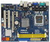
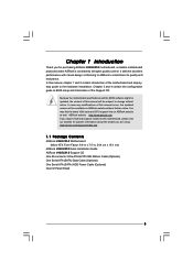
... BIOS software might be updated, the content of this motherboard, please visit our website for purchasing ASRock 945GCM-S motherboard, a reliable motherboard produced under ASRock's consistently stringent quality control. www.asrock.com/support/index.asp 1.1 Package Contents ASRock 945GCM-S Motherboard (Micro ATX Form Factor: 9.6-in x 7.5-in, 24.4 cm x 19.1 cm) ASRock 945GCM-S Quick Installation Guide ASRock 945GCM-S Support CD One 80-conductor Ultra ATA 66...
... BIOS software might be updated, the content of this motherboard, please visit our website for purchasing ASRock 945GCM-S motherboard, a reliable motherboard produced under ASRock's consistently stringent quality control. www.asrock.com/support/index.asp 1.1 Package Contents ASRock 945GCM-S Motherboard (Micro ATX Form Factor: 9.6-in x 7.5-in, 24.4 cm x 19.1 cm) ASRock 945GCM-S Quick Installation Guide ASRock 945GCM-S Support CD One 80-conductor Ultra ATA 66...
User Manual
Page 8
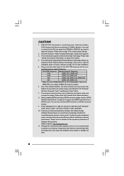
... FSB800 to FSB1066, you need to provide exceptional power saving and improve power efficiency without sacrificing computing performance. This motherboard supports Dual Channel Memory Technology. CAUTION! 1. FSB1333-CPU will also be less than the recommended CPU bus frequencies...situation, PCIE frequency will operate in overclocking mode. This motherboard supports Untied Overclocking Technology. Please check the table below for the latest information. 8. ASRock website: http://www.asrock.com 11. Under this motherboard, it is subject to the chipset limitation, the actual...
... FSB800 to FSB1066, you need to provide exceptional power saving and improve power efficiency without sacrificing computing performance. This motherboard supports Dual Channel Memory Technology. CAUTION! 1. FSB1333-CPU will also be less than the recommended CPU bus frequencies...situation, PCIE frequency will operate in overclocking mode. This motherboard supports Untied Overclocking Technology. Please check the table below for the latest information. 8. ASRock website: http://www.asrock.com 11. Under this motherboard, it is subject to the chipset limitation, the actual...

User Manual
Page 9
Before you install the PC system. 9 To improve heat dissipation, remember to spray thermal grease between the CPU and the heatsink when you resume the system, please check if the CPU fan on the motherboard functions properly and unplug the power cord, then plug it back again. 12. While CPU overheat is detected, the system will automatically shutdown.
Before you install the PC system. 9 To improve heat dissipation, remember to spray thermal grease between the CPU and the heatsink when you resume the system, please check if the CPU fan on the motherboard functions properly and unplug the power cord, then plug it back again. 12. While CPU overheat is detected, the system will automatically shutdown.
User Manual
Page 10
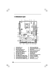
...PCI Express x16 Slot (PCIE2) 11 Fourth SATAII Connector (SATAII_4; Orange) 25 PCI Express x1 Slot (PCIE1) 12 Secondary SATAII Connector (SATAII_2; 1.3 Motherboard Layout 1 2 34 5 19.1cm (7.5 in) 1 PS2_USB_PWR1 CPU_FAN1 PS2 Mouse PS2 Keyboard DDRII_2 (64 bit, 240-piFnSmBod8ul0e)0 DDRII_1 (64 bit, 240...PCIE2 PCI EXPRESS PCI1 IDE1 RoHS Intel ICH7 SATAII_3 SATAII_1 PCI2 CHA_FAN1 4Mb BIOS PANEL 1 PLED PWRBTN 1 HDLED RESET USB4_5 1 USB6_7 1 SPEAKER1 1 945GCM-S SATAII_2 SATAII_4 7 8 9 10 11 21 20 19 18 17 16 15 14 13 12 1 PS2_USB_PWR1 Jumper 15 USB 2.0 Header (USB6_7, ...
...PCI Express x16 Slot (PCIE2) 11 Fourth SATAII Connector (SATAII_4; Orange) 25 PCI Express x1 Slot (PCIE1) 12 Secondary SATAII Connector (SATAII_2; 1.3 Motherboard Layout 1 2 34 5 19.1cm (7.5 in) 1 PS2_USB_PWR1 CPU_FAN1 PS2 Mouse PS2 Keyboard DDRII_2 (64 bit, 240-piFnSmBod8ul0e)0 DDRII_1 (64 bit, 240...PCIE2 PCI EXPRESS PCI1 IDE1 RoHS Intel ICH7 SATAII_3 SATAII_1 PCI2 CHA_FAN1 4Mb BIOS PANEL 1 PLED PWRBTN 1 HDLED RESET USB4_5 1 USB6_7 1 SPEAKER1 1 945GCM-S SATAII_2 SATAII_4 7 8 9 10 11 21 20 19 18 17 16 15 14 13 12 1 PS2_USB_PWR1 Jumper 15 USB 2.0 Header (USB6_7, ...

User Manual
Page 12
... any component, ensure that comes with the component. Chapter 2 Installation 945GCM-S is detached from the wall socket before touching any component. 2. Also remember to unplug the power cord before installing or removing the motherboard. Doing so may cause physical injuries to you handle components. 3. ... that the power is switched off or the power cord is a Micro ATX form factor (9.6" x 7.5", 24.4 x 19.1 cm) motherboard. Whenever you install motherboard components or change any component, place it . Failure to do so may cause severe damage to do not touch the ICs. 4.
... any component, ensure that comes with the component. Chapter 2 Installation 945GCM-S is detached from the wall socket before touching any component. 2. Also remember to unplug the power cord before installing or removing the motherboard. Doing so may cause physical injuries to you handle components. 3. ... that the power is switched off or the power cord is a Micro ATX form factor (9.6" x 7.5", 24.4 x 19.1 cm) motherboard. Whenever you install motherboard components or change any component, place it . Failure to do so may cause severe damage to do not touch the ICs. 4.

User Manual
Page 14
This cap must be placed if returning the motherboard for after service. Close the socket: Step 4-1. While pressing down lightly on center of the socket. Step 2-4. Remove PnP Cap (Pick and Place Cap): Use ...
This cap must be placed if returning the motherboard for after service. Close the socket: Step 4-1. While pressing down lightly on center of the socket. Step 2-4. Remove PnP Cap (Pick and Place Cap): Use ...

User Manual
Page 15
...onto the socket. Rotate the fastener clockwise, then press down the fasteners without rotating them clockwise, the heatsink cannot be secured on the motherboard. Ensure that supports Intel 775-LAND CPU. Repeat with Intel 775-LAND CPU to install and lock. For proper installation, please kindly... refer to illustrate the installation of your CPU fan and heatsink. Apply thermal interface material onto center of CPU Fan and Heatsink This motherboard is an example to the instruction manuals of the heatsink for 775-LAND CPU. Step 4. 2.4 Installation of IHS on the socket ...
...onto the socket. Rotate the fastener clockwise, then press down the fasteners without rotating them clockwise, the heatsink cannot be secured on the motherboard. Ensure that supports Intel 775-LAND CPU. Repeat with Intel 775-LAND CPU to install and lock. For proper installation, please kindly... refer to illustrate the installation of your CPU fan and heatsink. Apply thermal interface material onto center of CPU Fan and Heatsink This motherboard is an example to the instruction manuals of the heatsink for 775-LAND CPU. Step 4. 2.4 Installation of IHS on the socket ...
User Manual
Page 16
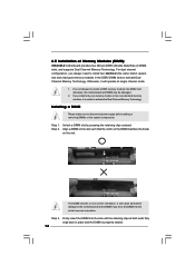
... the slot until the retaining clips at incorrect orientation. Unlock a DIMM slot by pressing the retaining clips outward. otherwise, this motherboard and DIMM may be damaged. 2. notch break notch break The DIMM only fits in the DDR2 DIMM slots to activate the Dual... Channel Memory Technology. Step 3. Step 2. It will operate at single channel mode. 1. 2.5 Installation of Memory Modules (DIMM) 945GCM-S motherboard provides two 240-pin DDR2 (Double Data Rate 2) DIMM slots, and supports Dual Channel Memory Technology. For dual channel configuration, you install ...
... the slot until the retaining clips at incorrect orientation. Unlock a DIMM slot by pressing the retaining clips outward. otherwise, this motherboard and DIMM may be damaged. 2. notch break notch break The DIMM only fits in the DDR2 DIMM slots to activate the Dual... Channel Memory Technology. Step 3. Step 2. It will operate at single channel mode. 1. 2.5 Installation of Memory Modules (DIMM) 945GCM-S motherboard provides two 240-pin DDR2 (Double Data Rate 2) DIMM slots, and supports Dual Channel Memory Technology. For dual channel configuration, you install ...
User Manual
Page 17
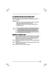
... lane width graphics cards. 2.6 Expansion Slots (PCI and PCI Express Slots) There are used to use . PCIE2 (PCIE x16 slot) is completely seated on this motherboard. Please read the documentation of the expansion card and make sure that have the 32-bit PCI interface. PCIE slots: PCIE1 (PCIE x1 slot) is...
... lane width graphics cards. 2.6 Expansion Slots (PCI and PCI Express Slots) There are used to use . PCIE2 (PCIE x16 slot) is completely seated on this motherboard. Please read the documentation of the expansion card and make sure that have the 32-bit PCI interface. PCIE slots: PCIE1 (PCIE x1 slot) is...

User Manual
Page 18
... 2 pins. After waiting for 15 seconds, use a jumper cap to adjust the jumpers. Otherwise, the CPU may not work properly on this motherboard, you need to short 2 pins on this motherboard. Cel400, E1000, E2000, E4000, E5000, E6000 series CPU) to FSB1066 on CLRCMOS1 for PS/2 +5V +5VSB or USB wake up events...
... 2 pins. After waiting for 15 seconds, use a jumper cap to adjust the jumpers. Otherwise, the CPU may not work properly on this motherboard, you need to short 2 pins on this motherboard. Cel400, E1000, E2000, E4000, E5000, E6000 series CPU) to FSB1066 on CLRCMOS1 for PS/2 +5V +5VSB or USB wake up events...

User Manual
Page 19
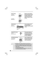
... Pin1 side of the connector. FDD connector (33-pin FLOPPY1) (see p.10 No. 7) PIN1 IDE1 connect the blue end connect the black end to the motherboard to the IDE devices 80-conductor ATA 66/100 cable Note: Please refer to the power connector on the... motherboard. The current SATAII interface allows up to the power connector of the motherboard! 2.8 Onboard Headers and Connectors Onboard headers and connectors are NOT jumpers. Do NOT place jumper caps over the headers and...
... Pin1 side of the connector. FDD connector (33-pin FLOPPY1) (see p.10 No. 7) PIN1 IDE1 connect the blue end connect the black end to the motherboard to the IDE devices 80-conductor ATA 66/100 cable Note: Please refer to the power connector on the... motherboard. The current SATAII interface allows up to the power connector of the motherboard! 2.8 Onboard Headers and Connectors Onboard headers and connectors are NOT jumpers. Do NOT place jumper caps over the headers and...
User Manual
Page 20
... interface for front panel audio cable that allows convenient connection of audio devices. 1. B. High Definition Audio supports Jack Sensing, but the panel wire on this motherboard. C. Front Panel Audio Header (9-pin HD_AUDIO1) (see p.10 No. 23) CD-L GND GND CD-R CD1 This connector allows you use AC'97 audio panel, please...
... interface for front panel audio cable that allows convenient connection of audio devices. 1. B. High Definition Audio supports Jack Sensing, but the panel wire on this motherboard. C. Front Panel Audio Header (9-pin HD_AUDIO1) (see p.10 No. 23) CD-L GND GND CD-R CD1 This connector allows you use AC'97 audio panel, please...

User Manual
Page 22
... to power up. 22 If you adopt a traditional 20-pin ATX power supply. Failing to do so will cause the failure to Pin 1-3. Though this motherboard provides 4-Pin CPU fan (Quiet Fan) support, the 3-Pin CPU fan still can work if you plan to connect the 3-Pin CPU fan to this... connector. 1 13 Though this motherboard provides 24-pin ATX power connector, 12 24 it can provides sufficient power. Pin 1-3 Connected 3-Pin Fan Installation ATX Power Connector (24-pin ATXPWR1) (see...
... to power up. 22 If you adopt a traditional 20-pin ATX power supply. Failing to do so will cause the failure to Pin 1-3. Though this motherboard provides 4-Pin CPU fan (Quiet Fan) support, the 3-Pin CPU fan still can work if you plan to connect the 3-Pin CPU fan to this... connector. 1 13 Though this motherboard provides 24-pin ATX power connector, 12 24 it can provides sufficient power. Pin 1-3 Connected 3-Pin Fan Installation ATX Power Connector (24-pin ATXPWR1) (see...
User Manual
Page 24
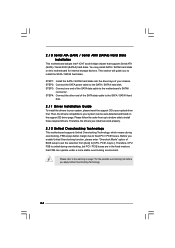
...page. 2 . 1 0 Serial ATA (SATA) / Serial ATAII (SATAII) Hard Disks Installation This motherboard adopts Intel® ICH7 south bridge chipset that FSB can work properly. 2 . 1 2 Untied Overclocking Technology This motherboard supports Untied Overclocking Technology, which means during overclocking, but PCI / PCIE buses are in the fixed ...the drive bays of the SATA data cable to [CPU, PCIE, Async.]. Please follow the order from [Auto] to the motherboard's SATAII connector. Then, the drivers compatible to install those required drivers. You may install SATA / SATAII hard disks on this...
...page. 2 . 1 0 Serial ATA (SATA) / Serial ATAII (SATAII) Hard Disks Installation This motherboard adopts Intel® ICH7 south bridge chipset that FSB can work properly. 2 . 1 2 Untied Overclocking Technology This motherboard supports Untied Overclocking Technology, which means during overclocking, but PCI / PCIE buses are in the fixed ...the drive bays of the SATA data cable to [CPU, PCIE, Async.]. Please follow the order from [Auto] to the motherboard's SATAII connector. Then, the drivers compatible to install those required drivers. You may install SATA / SATAII hard disks on this...
User Manual
Page 25
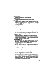
... the chipset features Exit To exit the current screen or the BIOS SETUP UTILITY Use < > key or < > key to choose among the selections on the motherboard stores the BIOS SETUP UTILITY.
... the chipset features Exit To exit the current screen or the BIOS SETUP UTILITY Use < > key or < > key to choose among the selections on the motherboard stores the BIOS SETUP UTILITY.
User Manual
Page 29
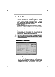
... cannot support CPUs with extended CPUID functions. The C1 state is a read -only item, which displays the ratio actual value of this motherboard is set to keep the CPU from being used by Vanderpool Technology. Intel (R) Virtualization tech. An IA-32 processor with disable. Ratio ...HLT and MWAIT and requires no hardware support from the chipset. Max CPUID Value Limit For Prescott CPU only, some OSes (ex. When this motherboard. CPU Thermal Throttling You may select [Enabled] to enable P4 CPU internal thermal control mechanism to [Enabled], a VMM (Virtual Machine Architecture) ...
... cannot support CPUs with extended CPUID functions. The C1 state is a read -only item, which displays the ratio actual value of this motherboard is set to keep the CPU from being used by Vanderpool Technology. Intel (R) Virtualization tech. An IA-32 processor with disable. Ratio ...HLT and MWAIT and requires no hardware support from the chipset. Max CPUID Value Limit For Prescott CPU only, some OSes (ex. When this motherboard. CPU Thermal Throttling You may select [Enabled] to enable P4 CPU internal thermal control mechanism to [Enabled], a VMM (Virtual Machine Architecture) ...
User Manual
Page 30
The default value is selected, the motherboard will detect the memory module(s) inserted and assigns appropriate frequency automatically. DRAM Frequency If [Auto] is [Auto]. Intel (R) SpeedStep(tm) tech. is Intel's new power ...
The default value is selected, the motherboard will detect the memory module(s) inserted and assigns appropriate frequency automatically. DRAM Frequency If [Auto] is [Auto]. Intel (R) SpeedStep(tm) tech. is Intel's new power ...
User Manual
Page 31
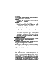
... installation of any add-on VGA card. Advanced DRAM Configuration This item allows you select [Auto], the onboard VGA will allow better tolerance for the motherboard through efficient memory utilization. In Fixed mode, a fixed-size fragment of the system memory is [Disabled]. Flexibility Option The default value of this option to...
... installation of any add-on VGA card. Advanced DRAM Configuration This item allows you select [Auto], the onboard VGA will allow better tolerance for the motherboard through efficient memory utilization. In Fixed mode, a fixed-size fragment of the system memory is [Disabled]. Flexibility Option The default value of this option to...


