
User Manual
Page 4
... 3.4 Advanced Screen 48 3.4.1 CPU Configuration 49 3.4.2 Chipset Configuration 50 3.4.3 ACPI Configuration 51 3.4.4 Storage Configuration 52 3.4.5 PCIPnP Configuration 54 3.4.6 Floppy Configuration 54 3.4.7 Super IO Configuration 55 3.4.8 USB Configuration 56 3.5 Hardware Health Event Monitoring Screen 57 3.6 Boot Screen 58 3.6.1 Boot Settings Configuration 58 3.7 Security Screen 59 3.8 Exit Screen 60 4 . 3 .
... 3.4 Advanced Screen 48 3.4.1 CPU Configuration 49 3.4.2 Chipset Configuration 50 3.4.3 ACPI Configuration 51 3.4.4 Storage Configuration 52 3.4.5 PCIPnP Configuration 54 3.4.6 Floppy Configuration 54 3.4.7 Super IO Configuration 55 3.4.8 USB Configuration 56 3.5 Hardware Health Event Monitoring Screen 57 3.6 Boot Screen 58 3.6.1 Boot Settings Configuration 58 3.7 Security Screen 59 3.8 Exit Screen 60 4 . 3 .

User Manual
Page 7
...LED) - Front panel audio connector - 3 x USB 2.0 headers (support 6 USB 2.0 ports) - 8Mb AMI BIOS - Premium Blu-ray audio support - CD in / Front Speaker/Microphone (see CAUTION 6) - 1 x USB 3.0 port by Fresco FL1000G, supports USB 3.0 up to -Use USB 3.0 Port - 1 x RJ-45 LAN Port with... - 1 x PS/2 Keyboard Port - 1 x VGA/D-Sub Port - 1 x VGA/DVI-D Port - 1 x HDMI Port - 1 x Optical SPDIF Out Port - 5 x Ready-to-Use USB 2.0 Ports - 1 x eSATAII Connector - 1 x Ready-to 5Gb/s - 5 x Serial ATAII 3.0Gb/s connectors, support RAID (RAID 0, RAID 1, RAID 10 and JBOD), NCQ, AHCI and "Hot...
...LED) - Front panel audio connector - 3 x USB 2.0 headers (support 6 USB 2.0 ports) - 8Mb AMI BIOS - Premium Blu-ray audio support - CD in / Front Speaker/Microphone (see CAUTION 6) - 1 x USB 3.0 port by Fresco FL1000G, supports USB 3.0 up to -Use USB 3.0 Port - 1 x RJ-45 LAN Port with... - 1 x PS/2 Keyboard Port - 1 x VGA/D-Sub Port - 1 x VGA/DVI-D Port - 1 x HDMI Port - 1 x Optical SPDIF Out Port - 5 x Ready-to-Use USB 2.0 Ports - 1 x eSATAII Connector - 1 x Ready-to 5Gb/s - 5 x Serial ATAII 3.0Gb/s connectors, support RAID (RAID 0, RAID 1, RAID 10 and JBOD), NCQ, AHCI and "Hot...

User Manual
Page 10
... a profile and share with your BIOS only in Flash ROM. Although this motherboard offers stepless control, it back again. According to access ASRock Instant Flash. Just launch this utility, you what it is not recommended to record the OC settings and share with the power supply manufacturer...systems first like MS-DOS or Windows®. This convenient BIOS update tool allows you to your USB flash drive, floppy disk or hard drive, then you can update your friends! ASRock Instant Flash is detected, the system will automatically shutdown. Please be shared and worked on the ...
... a profile and share with your BIOS only in Flash ROM. Although this motherboard offers stepless control, it back again. According to access ASRock Instant Flash. Just launch this utility, you what it is not recommended to record the OC settings and share with the power supply manufacturer...systems first like MS-DOS or Windows®. This convenient BIOS update tool allows you to your USB flash drive, floppy disk or hard drive, then you can update your friends! ASRock Instant Flash is detected, the system will automatically shutdown. Please be shared and worked on the ...

User Manual
Page 12
...channel speaker, please connect the speaker's plug into "Front Speaker Jack". 1.4 I/O Panel 1 2 34 58 69 7 10 16 15 14 13 12 11 1 USB 2.0 Ports (USB23) 2 VGA/D-Sub Port 3 USB 2.0 Ports (USB45) * 4 LAN RJ-45 Port 5 Central / Bass (Orange) 6 Rear Speaker (Black) 7 Optical SPDIF Out Port 8 Line In (...Light Blue) ** 9 Front Speaker (Lime) 10 Microphone (Pink) 11 USB 2.0 Port (USB0) 12 USB 3.0 Port (USB1) 13 eSATAII Port (eSATA1) 14 VGA/HDMI Port 15 VGA/DVI-D Port 16 PS/2 Keyboard Port (Purple) * There are allowed to...
...channel speaker, please connect the speaker's plug into "Front Speaker Jack". 1.4 I/O Panel 1 2 34 58 69 7 10 16 15 14 13 12 11 1 USB 2.0 Ports (USB23) 2 VGA/D-Sub Port 3 USB 2.0 Ports (USB45) * 4 LAN RJ-45 Port 5 Central / Bass (Orange) 6 Rear Speaker (Black) 7 Optical SPDIF Out Port 8 Line In (...Light Blue) ** 9 Front Speaker (Lime) 10 Microphone (Pink) 11 USB 2.0 Port (USB0) 12 USB 3.0 Port (USB1) 13 eSATAII Port (eSATA1) 14 VGA/HDMI Port 15 VGA/DVI-D Port 16 PS/2 Keyboard Port (Purple) * There are allowed to...

User Manual
Page 23
When you select +5V_DUAL, USB devices can wake up events. To support ErP/EuP requirement, please set this jumper to short pin2 and pin3 on CLRCMOS1 for 15 seconds, use a ...
When you select +5V_DUAL, USB devices can wake up events. To support ErP/EuP requirement, please set this jumper to short pin2 and pin3 on CLRCMOS1 for 15 seconds, use a ...

User Manual
Page 25
... 1 GND P+6 P-6 USB_PWR USB_PWR P-9 P+9 GND DUMMY 1 GND P+8 P-8 USB_PWR USB_PWR P-11 P+11 GND DUMMY 1 GND P+10 P-10 USB_PWR IRTX +5V DUMMY 1 GND IRRX Besides five default USB 2.0 ports on the I/O panel, there are three USB 2.0 headers on the chassis must support HDA to receive stereo audio input from sound sources such as below...: A. C. USB 2.0 Headers (9-pin USB6_7) (see p.11 No. 11) (9-pin USB8_9) (see p.11 No. 13) (9-pin USB10_11) (see p.11 No. 23) Infrared Module Header (5-pin IR1) (see...
... 1 GND P+6 P-6 USB_PWR USB_PWR P-9 P+9 GND DUMMY 1 GND P+8 P-8 USB_PWR USB_PWR P-11 P+11 GND DUMMY 1 GND P+10 P-10 USB_PWR IRTX +5V DUMMY 1 GND IRRX Besides five default USB 2.0 ports on the I/O panel, there are three USB 2.0 headers on the chassis must support HDA to receive stereo audio input from sound sources such as below...: A. C. USB 2.0 Headers (9-pin USB6_7) (see p.11 No. 11) (9-pin USB8_9) (see p.11 No. 13) (9-pin USB10_11) (see p.11 No. 23) Infrared Module Header (5-pin IR1) (see...

User Manual
Page 48
CPU Configuration Chipset Configuration ACPI Configuration Storage Configuration PCIPnP Configuration Floppy Configuration SuperIO Configuration USB Configuration BIOS Update Utility ASRock Instant Flash Select Screen Select Item Enter Go to update your BIOS, and reboot your BIOS only in a few clicks without entering operating systems first ...
CPU Configuration Chipset Configuration ACPI Configuration Storage Configuration PCIPnP Configuration Floppy Configuration SuperIO Configuration USB Configuration BIOS Update Utility ASRock Instant Flash Select Screen Select Item Enter Go to update your BIOS, and reboot your BIOS only in a few clicks without entering operating systems first ...

User Manual
Page 56
... under BIOS setup and Windows / Linux OS. Enables support for USB devices. USB devices are not allowed to select legacy support for legacy USB. [Auto] - Enables legacy support if USB devices are four configuration options: [Enabled], [Auto], [Disabled] ... [Enabled] - USB devices are allowed to below descriptions for the details of USB controller. 3.4.8 USB Configuration BIOS SETUP UTILITY Advanced USB Configuration USB Controller USB 2.0 Support Legacy USB Support USB 3.0 Controller [Enabled] [Enabled] [Enabled] [Enabled] To enable or disable the onboard USB controllers. +F1 F9...
... under BIOS setup and Windows / Linux OS. Enables support for USB devices. USB devices are not allowed to select legacy support for legacy USB. [Auto] - Enables legacy support if USB devices are four configuration options: [Enabled], [Auto], [Disabled] ... [Enabled] - USB devices are allowed to below descriptions for the details of USB controller. 3.4.8 USB Configuration BIOS SETUP UTILITY Advanced USB Configuration USB Controller USB 2.0 Support Legacy USB Support USB 3.0 Controller [Enabled] [Enabled] [Enabled] [Enabled] To enable or disable the onboard USB controllers. +F1 F9...

User Manual
Page 58
... Change Option General Help Load Defaults Save and Exit Exit v02.54 (C) Copyright 1985-2003, American Megatrends, Inc. The default value is [Enabled]. 58 ROM C] [USB] Select Screen Select Item Enter Go to configure the boot settings and the boot priority. AddOn ROM Display Use this item to see the AddOn...
... Change Option General Help Load Defaults Save and Exit Exit v02.54 (C) Copyright 1985-2003, American Megatrends, Inc. The default value is [Enabled]. 58 ROM C] [USB] Select Screen Select Item Enter Go to configure the boot settings and the boot priority. AddOn ROM Display Use this item to see the AddOn...

Quick Installation Guide
Page 2
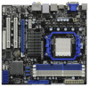
... Retention Module 22 Chassis Speaker Header 5 AM3 CPU Socket (SPEAKER 1, White) 6 2 x 240-pin DDR3 DIMM Slots 23 USB 2.0 Header (USB10_11, Blue) (Dual Channel A: DDR3_A1, DDR3_B1; White) 26 Floppy Connector (FLOPPY1) 8 ATX Power Connector (ATXPWR1...USB 2.0 Header (USB8_9, Blue) 31 PCI Express 2.0 x16 Slot (PCIE2; White) 15 SPI Flash Memory (8Mb) 33 Power Fan Connector (PWR_FAN1) 16 SATAII Connector (SATAII_5 (PORT 4), Blue) 34 Northbridge Controller 17 SATAII Connector (SATAII_4 (PORT 3), Blue) 35 USB_PW2 Jumper 18 SATAII Connector (SATAII_3 (PORT 2), Blue) 2 ASRock 880GMH/USB3...
... Retention Module 22 Chassis Speaker Header 5 AM3 CPU Socket (SPEAKER 1, White) 6 2 x 240-pin DDR3 DIMM Slots 23 USB 2.0 Header (USB10_11, Blue) (Dual Channel A: DDR3_A1, DDR3_B1; White) 26 Floppy Connector (FLOPPY1) 8 ATX Power Connector (ATXPWR1...USB 2.0 Header (USB8_9, Blue) 31 PCI Express 2.0 x16 Slot (PCIE2; White) 15 SPI Flash Memory (8Mb) 33 Power Fan Connector (PWR_FAN1) 16 SATAII Connector (SATAII_5 (PORT 4), Blue) 34 Northbridge Controller 17 SATAII Connector (SATAII_4 (PORT 3), Blue) 35 USB_PW2 Jumper 18 SATAII Connector (SATAII_3 (PORT 2), Blue) 2 ASRock 880GMH/USB3...

Quick Installation Guide
Page 3
...-- -- -- 4 V V -- -- 6 V V V -- 8 V V V V To enable Multi-Streaming function, you need to connect a front panel audio cable to use front panel audio. 3 ASRock 880GMH/USB3 Motherboard English Please select "Mixer ToolBox" , click "Enable playback multi-streaming", and click "ok". Choose "2CH", "4CH", "6CH", or "8CH" and then you use. LAN...Black) 7 Optical SPDIF Out Port 8 Line In (Light Blue) ** 9 Front Speaker (Lime) 10 Microphone (Pink) 11 USB 2.0 Port (USB0) 12 USB 3.0 Port (USB1) 13 eSATAII Port (eSATA1) 14 VGA/HDMI Port 15 VGA/DVI-D Port 16 PS/2 Keyboard Port (...
...-- -- -- 4 V V -- -- 6 V V V -- 8 V V V V To enable Multi-Streaming function, you need to connect a front panel audio cable to use front panel audio. 3 ASRock 880GMH/USB3 Motherboard English Please select "Mixer ToolBox" , click "Enable playback multi-streaming", and click "ok". Choose "2CH", "4CH", "6CH", or "8CH" and then you use. LAN...Black) 7 Optical SPDIF Out Port 8 Line In (Light Blue) ** 9 Front Speaker (Lime) 10 Microphone (Pink) 11 USB 2.0 Port (USB0) 12 USB 3.0 Port (USB1) 13 eSATAII Port (eSATA1) 14 VGA/HDMI Port 15 VGA/DVI-D Port 16 PS/2 Keyboard Port (...

Quick Installation Guide
Page 6
...Supports "Plug and Play" - VCCM, NB, SB Voltage Multi-adjustment English 6 ASRock 880GMH/USB3 Motherboard HD Audio Jack: Rear Speaker/Central/Bass/Line in header - Supports jumperfree - Front panel audio connector - 3 x USB 2.0 headers (support 6 USB 2.0 ports) - 8Mb AMI BIOS - Audio LAN Rear Panel I /O Panel -...x PS/2 Keyboard Port - 1 x VGA/D-Sub Port - 1 x VGA/DVI-D Port - 1 x HDMI Port - 1 x Optical SPDIF Out Port - 5 x Ready-to-Use USB 2.0 Ports - 1 x eSATAII Connector - 1 x Ready-to 5Gb/s - 5 x Serial ATAII 3.0Gb/s connectors, support RAID (RAID 0, RAID 1, RAID 10 and JBOD), NCQ, ...
...Supports "Plug and Play" - VCCM, NB, SB Voltage Multi-adjustment English 6 ASRock 880GMH/USB3 Motherboard HD Audio Jack: Rear Speaker/Central/Bass/Line in header - Supports jumperfree - Front panel audio connector - 3 x USB 2.0 headers (support 6 USB 2.0 ports) - 8Mb AMI BIOS - Audio LAN Rear Panel I /O Panel -...x PS/2 Keyboard Port - 1 x VGA/D-Sub Port - 1 x VGA/DVI-D Port - 1 x HDMI Port - 1 x Optical SPDIF Out Port - 5 x Ready-to-Use USB 2.0 Ports - 1 x eSATAII Connector - 1 x Ready-to 5Gb/s - 5 x Serial ATAII 3.0Gb/s connectors, support RAID (RAID 0, RAID 1, RAID 10 and JBOD), NCQ, ...
Quick Installation Guide
Page 9
...with the power supply manufacturer for the user to EuP, the total AC power of the completed system shall be noticed that the USB flash drive or hard drive must meet EuP standard, an EuP ready motherboard and an EuP ready power supply are required. For ...noted that the OC profile can update your friends! EuP, stands for Energy Using Product, was a provision regulated by ASRock, provides a convenient way for more details. 9 ASRock 880GMH/USB3 Motherboard English Just launch this motherboard offers stepless control, it back again. It helps you to save the new BIOS ...
...with the power supply manufacturer for the user to EuP, the total AC power of the completed system shall be noticed that the USB flash drive or hard drive must meet EuP standard, an EuP ready motherboard and an EuP ready power supply are required. For ...noted that the OC profile can update your friends! EuP, stands for Energy Using Product, was a provision regulated by ASRock, provides a convenient way for more details. 9 ASRock 880GMH/USB3 Motherboard English Just launch this motherboard offers stepless control, it back again. It helps you to save the new BIOS ...

Quick Installation Guide
Page 20
... standby current provided by power supply. When you to enable (see p.2, No. 24) Default Clear CMOS Note: CLRCMOS1 allows you select +5V_DUAL, USB devices can wake up events. To clear and reset the system parameters to +5V. USB_PW1 Short pin2, pin3 to clear the data in CMOS includes...default setup, please turn off the computer and unplug the power cord from the power supply. However, please do the clear-CMOS action. 20 ASRock 880GMH/USB3 Motherboard When the jumper cap is placed on pins, the jumper is placed on these 2 pins. After waiting for 15 seconds, use a jumper...
... standby current provided by power supply. When you to enable (see p.2, No. 24) Default Clear CMOS Note: CLRCMOS1 allows you select +5V_DUAL, USB devices can wake up events. To clear and reset the system parameters to +5V. USB_PW1 Short pin2, pin3 to clear the data in CMOS includes...default setup, please turn off the computer and unplug the power cord from the power supply. However, please do the clear-CMOS action. 20 ASRock 880GMH/USB3 Motherboard When the jumper cap is placed on pins, the jumper is placed on these 2 pins. After waiting for 15 seconds, use a jumper...

Quick Installation Guide
Page 22
...instruction in our manual and chassis manual to function correctly. If you CD1 to Ground (GND). 22 ASRock 880GMH/USB3 Motherboard English Connect Mic_IN (MIC) to OUT2_L. Each USB 2.0 header can support two USB 2.0 ports. Connect Audio_R (RIN) to OUT2_R and Audio_L (LIN) to MIC2_L. Infrared Module Header (5-...(CD1: see p.2 No. 28) Front Panel Audio Header (9-pin HD_AUDIO1) (see p.2 No. 23) Besides five default USB 2.0 ports on the I/O panel, there are three USB 2.0 headers on the chassis must support HDA to install your system. 2. C. This is an interface for the front panel...
...instruction in our manual and chassis manual to function correctly. If you CD1 to Ground (GND). 22 ASRock 880GMH/USB3 Motherboard English Connect Mic_IN (MIC) to OUT2_L. Each USB 2.0 header can support two USB 2.0 ports. Connect Audio_R (RIN) to OUT2_R and Audio_L (LIN) to MIC2_L. Infrared Module Header (5-...(CD1: see p.2 No. 28) Front Panel Audio Header (9-pin HD_AUDIO1) (see p.2 No. 23) Besides five default USB 2.0 ports on the I/O panel, there are three USB 2.0 headers on the chassis must support HDA to install your system. 2. C. This is an interface for the front panel...


