User Manual
Page 4
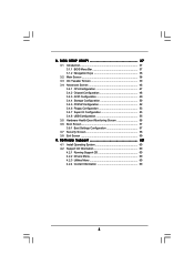
... 3.4 Advanced Screen 46 3.4.1 CPU Configuration 47 3.4.2 Chipset Configuration 48 3.4.3 ACPI Configuration 49 3.4.4 Storage Configuration 50 3.4.5 PCIPnP Configuration 52 3.4.6 Floppy Configuration 53 3.4.7 Super IO Configuration 53 3.4.8 USB Configuration 55 3.5 Hardware Health Event Monitoring Screen 56 3.6 Boot Screen 57 3.6.1 Boot Settings Configuration 57 3.7 Security Screen 58 3.8 Exit Screen 59 4 . Software Support 60 4.1 Install...
... 3.4 Advanced Screen 46 3.4.1 CPU Configuration 47 3.4.2 Chipset Configuration 48 3.4.3 ACPI Configuration 49 3.4.4 Storage Configuration 50 3.4.5 PCIPnP Configuration 52 3.4.6 Floppy Configuration 53 3.4.7 Super IO Configuration 53 3.4.8 USB Configuration 55 3.5 Hardware Health Event Monitoring Screen 56 3.6 Boot Screen 57 3.6.1 Boot Settings Configuration 57 3.7 Security Screen 58 3.8 Exit Screen 59 4 . Software Support 60 4.1 Install...
User Manual
Page 7
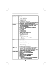
... Flash (see CAUTION 9) - Intelligent Energy Saver (see CAUTION 10) - HD Audio Jack: Line in header - Front panel audio connector - 3 x USB 2.0 headers (support 6 USB 2.0 ports) (see CAUTION 8) - ASRock OC Tuner (see CAUTION 7) - 8Mb AMI BIOS - ASRock OC DNA (see CAUTION 6) - 1 x ATA133 IDE connector (supports 2 x IDE devices) - 1 x Floppy connector - 1 x IR header - 1 x Print port header - 1 x COM port...
... Flash (see CAUTION 9) - Intelligent Energy Saver (see CAUTION 10) - HD Audio Jack: Line in header - Front panel audio connector - 3 x USB 2.0 headers (support 6 USB 2.0 ports) (see CAUTION 8) - ASRock OC Tuner (see CAUTION 7) - 8Mb AMI BIOS - ASRock OC DNA (see CAUTION 6) - 1 x ATA133 IDE connector (supports 2 x IDE devices) - 1 x Floppy connector - 1 x IR header - 1 x Print port header - 1 x COM port...
User Manual
Page 8
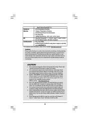
... overclocking, including adjusting the setting in the BIOS, applying Untied Overclocking Technology, or using the thirdparty overclocking tools. Please check AMD website for USB 2.0 works fine under Windows® 7 / VistaTM / XP. Boot Failure Guard (B.F.G.) Hardware - It should be less than 4GB for the...Ready (ErP/EuP ready power supply is required) (see CAUTION 14) * For detailed product information, please visit our website: http://www.asrock.com WARNING Please realize that there is a certain risk involved with 64-bit CPU, there is subject to SATAII connector directly. 7. You ...
... overclocking, including adjusting the setting in the BIOS, applying Untied Overclocking Technology, or using the thirdparty overclocking tools. Please check AMD website for USB 2.0 works fine under Windows® 7 / VistaTM / XP. Boot Failure Guard (B.F.G.) Hardware - It should be less than 4GB for the...Ready (ErP/EuP ready power supply is required) (see CAUTION 14) * For detailed product information, please visit our website: http://www.asrock.com WARNING Please realize that there is a certain risk involved with 64-bit CPU, there is subject to SATAII connector directly. 7. You ...
User Manual
Page 9
... the operating system and simplifies the complicated recording process of . Please visit our website for the operation procedures of output phases to access ASRock Instant Flash. OC DNA literally tells you install the PC system. 9 Frequencies other complicated flash utility. OC DNA, an exclusive utility...shared and worked on the motherboard functions properly and unplug the power cord, then plug it is a user-friendly ASRock overclocking tool which allows you to your USB flash drive, floppy disk or hard drive, then you resume the system, please check if the CPU fan on...
... the operating system and simplifies the complicated recording process of . Please visit our website for the operation procedures of output phases to access ASRock Instant Flash. OC DNA literally tells you install the PC system. 9 Frequencies other complicated flash utility. OC DNA, an exclusive utility...shared and worked on the motherboard functions properly and unplug the power cord, then plug it is a user-friendly ASRock overclocking tool which allows you to your USB flash drive, floppy disk or hard drive, then you resume the system, please check if the CPU fan on...
User Manual
Page 11
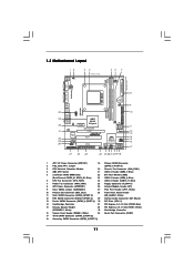
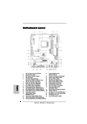
... 29 28 CMOS BATTERY USB 2.0 T: USB2 B: USB3 USB 2.0 T: USB4 B: USB5 CLRCMOS1 1 1 COM1 FSB2.6GHz Phenom USB 2.0 T: USB0 B: USB1 Top: RJ-45 Top: LINE IN Center: FRONT Bottom: MIC IN LAN AUDIO CODEC Super I/O CD1 1 HD_AUDIO1 LPT1 1 PCIE1 AMD 880G Chipset Hybrid CrossFire PCIE2 880GM-LE IDE1 PWR_FAN1 SATAII_4 SATAII_5 ... Connector 2 PS2_USB_PW1 Jumper (SATAII_1 (PORT 0)) 3 CPU Heatsink Retention Module 20 Chassis Fan Connector (CHA_FAN1) 4 AM3 CPU Socket 21 USB 2.0 Header (USB6_7, Blue) 5 2 x 240-pin DDR3 DIMM Slots 22 SPI Flash Memory (8Mb) (Dual Channel: DDR3_A1, DDR3_B1;
... 29 28 CMOS BATTERY USB 2.0 T: USB2 B: USB3 USB 2.0 T: USB4 B: USB5 CLRCMOS1 1 1 COM1 FSB2.6GHz Phenom USB 2.0 T: USB0 B: USB1 Top: RJ-45 Top: LINE IN Center: FRONT Bottom: MIC IN LAN AUDIO CODEC Super I/O CD1 1 HD_AUDIO1 LPT1 1 PCIE1 AMD 880G Chipset Hybrid CrossFire PCIE2 880GM-LE IDE1 PWR_FAN1 SATAII_4 SATAII_5 ... Connector 2 PS2_USB_PW1 Jumper (SATAII_1 (PORT 0)) 3 CPU Heatsink Retention Module 20 Chassis Fan Connector (CHA_FAN1) 4 AM3 CPU Socket 21 USB 2.0 Header (USB6_7, Blue) 5 2 x 240-pin DDR3 DIMM Slots 22 SPI Flash Memory (8Mb) (Dual Channel: DDR3_A1, DDR3_B1;

User Manual
Page 12
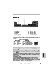
... 9 8 1 PS/2 Mouse Port (Green) 2 VGA/D-Sub Port 3 VGA/DVI-D Port * 4 RJ-45 Port 5 Line In (Light Blue) 6 Front Speaker (Lime) 7 Microphone (Pink) 8 USB 2.0 Ports (USB01) 9 USB 2.0 Ports (USB45) 10 USB 2.0 Ports (USB23) 11 PS/2 Keyboard Port (Purple) * There are allowed to select "Realtek HDA Primary output" to use Rear Speaker and Front Speaker...
... 9 8 1 PS/2 Mouse Port (Green) 2 VGA/D-Sub Port 3 VGA/DVI-D Port * 4 RJ-45 Port 5 Line In (Light Blue) 6 Front Speaker (Lime) 7 Microphone (Pink) 8 USB 2.0 Ports (USB01) 9 USB 2.0 Ports (USB45) 10 USB 2.0 Ports (USB23) 11 PS/2 Keyboard Port (Purple) * There are allowed to select "Realtek HDA Primary output" to use Rear Speaker and Front Speaker...
User Manual
Page 22
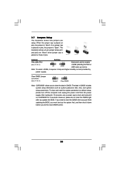
... Short pin2, pin3 to default setup, please turn off the computer and unplug the power cord from the power supply. After waiting for PS/2 or USB wake up the system first, and then shut it requires 2 Amp and higher standby current provided by power supply. When the jumper cap is placed...
... Short pin2, pin3 to default setup, please turn off the computer and unplug the power cord from the power supply. After waiting for PS/2 or USB wake up the system first, and then shut it requires 2 Amp and higher standby current provided by power supply. When the jumper cap is placed...
User Manual
Page 24
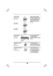
... can support two USB 2.0 ports. 1 GND P+6 P-6 USB_PWR AFD# ERROR# PINIT# SLIN# GND 1 SPD7 SPD6 ACK# SPD5 BUSY SPD4 PE SPD3 SLCT SPD2 SPD1 SPD0 STB# This is an interface ... P-11 P+11 GND DUMMY 1 GND P+10 P-10 USB_PWR USB_PWR P-9 P+9 GND DUMMY 1 GND P+8 P-8 USB_PWR USB_PWR P-7 P+7 GND DUMMY Besides six default USB 2.0 ports on the I/O panel, there are three USB 2.0 headers on this motherboard. USB 2.0 Headers (9-pin USB10_11) (see p.11 No. 24) (9-pin USB8_9) (see p.11 No. 23) (9-pin USB6_7) (see p.11 No. 21) Print...
... can support two USB 2.0 ports. 1 GND P+6 P-6 USB_PWR AFD# ERROR# PINIT# SLIN# GND 1 SPD7 SPD6 ACK# SPD5 BUSY SPD4 PE SPD3 SLCT SPD2 SPD1 SPD0 STB# This is an interface ... P-11 P+11 GND DUMMY 1 GND P+10 P-10 USB_PWR USB_PWR P-9 P+9 GND DUMMY 1 GND P+8 P-8 USB_PWR USB_PWR P-7 P+7 GND DUMMY Besides six default USB 2.0 ports on the I/O panel, there are three USB 2.0 headers on this motherboard. USB 2.0 Headers (9-pin USB10_11) (see p.11 No. 24) (9-pin USB8_9) (see p.11 No. 23) (9-pin USB6_7) (see p.11 No. 21) Print...

User Manual
Page 46
... Chipset Configuration ACPI Configuration Storage Configuration PCIPnP Configuration Floppy Configuration SuperIO Configuration USB Configuration BIOS Update Utility ASRock Instant Flash Select Screen Select Item Enter Go to update your BIOS, and reboot your BIOS only in Flash ROM. ASRock Instant Flash ASRock Instant Flash is a BIOS flash utility embedded in a few clicks without entering...
... Chipset Configuration ACPI Configuration Storage Configuration PCIPnP Configuration Floppy Configuration SuperIO Configuration USB Configuration BIOS Update Utility ASRock Instant Flash Select Screen Select Item Enter Go to update your BIOS, and reboot your BIOS only in Flash ROM. ASRock Instant Flash ASRock Instant Flash is a BIOS flash utility embedded in a few clicks without entering...
User Manual
Page 55
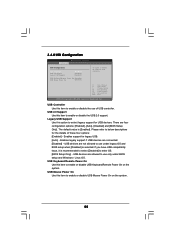
... to select legacy support for legacy USB. [Auto] - USB Mouse Power On Use this option to enable or disable USB Mouse Power On on the system. There are connected. [Disabled] - 3.4.8 USB Configuration BIOS SETUP UTILITY Advanced USB Configuration USB Controller USB 2.0 Support Legacy USB Support [Enabled] [Enabled] [Enabled] USB Keyboard/Remote Power On [Disabled] USB Mouse Power On [Disabled] To...
... to select legacy support for legacy USB. [Auto] - USB Mouse Power On Use this option to enable or disable USB Mouse Power On on the system. There are connected. [Disabled] - 3.4.8 USB Configuration BIOS SETUP UTILITY Advanced USB Configuration USB Controller USB 2.0 Support Legacy USB Support [Enabled] [Enabled] [Enabled] USB Keyboard/Remote Power On [Disabled] USB Mouse Power On [Disabled] To...

User Manual
Page 57
... Display Use this option to see the AddOn ROM information when the system boots, please select [Enabled]. CD - The default value is [Enabled]. 57 ROM C] [USB] Select Screen Select Item Enter Go to configure the boot settings and the boot priority. 3.6 Boot Screen In this section, it will display the available...
... Display Use this option to see the AddOn ROM information when the system boots, please select [Enabled]. CD - The default value is [Enabled]. 57 ROM C] [USB] Select Screen Select Item Enter Go to configure the boot settings and the boot priority. 3.6 Boot Screen In this section, it will display the available...
Quick Installation Guide
Page 2
... 34 Serial Port Connector (COM1) 17 Third SATAII Connector (SATAII_3 (PORT 2)) 18 Secondary SATAII Connector (SATAII_2 (PORT 1)) 2 ASRock 880GM-LE Motherboard Motherboard Layout English 1 ATX 12V Power Connector (ATX12V1) 19 Primary SATAII Connector 2 PS2_USB_PW1 Jumper (SATAII_1 (PORT 0)) 3 CPU... 2 x 240-pin DDR3 DIMM Slots 22 SPI Flash Memory (8Mb) (Dual Channel: DDR3_A1, DDR3_B1; Blue) 23 USB 2.0 Header (USB8_9, Blue) 6 CPU Fan Connector (CPU_FAN1) 24 USB 2.0 Header (USB10_11, Blue) 7 Power Fan Connector (PWR_FAN1) 25 Floppy Connector (FLOPPY1) 8 ATX Power Connector (ATXPWR1...
... 34 Serial Port Connector (COM1) 17 Third SATAII Connector (SATAII_3 (PORT 2)) 18 Secondary SATAII Connector (SATAII_2 (PORT 1)) 2 ASRock 880GM-LE Motherboard Motherboard Layout English 1 ATX 12V Power Connector (ATX12V1) 19 Primary SATAII Connector 2 PS2_USB_PW1 Jumper (SATAII_1 (PORT 0)) 3 CPU... 2 x 240-pin DDR3 DIMM Slots 22 SPI Flash Memory (8Mb) (Dual Channel: DDR3_A1, DDR3_B1; Blue) 23 USB 2.0 Header (USB8_9, Blue) 6 CPU Fan Connector (CPU_FAN1) 24 USB 2.0 Header (USB10_11, Blue) 7 Power Fan Connector (PWR_FAN1) 25 Floppy Connector (FLOPPY1) 8 ATX Power Connector (ATXPWR1...
Quick Installation Guide
Page 3
... Port 3 VGA/DVI-D Port * 4 RJ-45 Port 5 Line In (Light Blue) 6 Front Speaker (Lime) 7 Microphone (Pink) 8 USB 2.0 Ports (USB01) 9 USB 2.0 Ports (USB45) 10 USB 2.0 Ports (USB23) 11 PS/2 Keyboard Port (Purple) * There are allowed to select "Realtek HDA Primary output" to use Rear Speaker and ... the software setting of Multi-Streaming. Then reboot your computer, please double-click "Realtek HD Audio Manager" on your system. 3 ASRock 880GM-LE Motherboard English For Windows® 7 / VistaTM: After restarting your system. Set "Speaker Configuration" to the LAN port. Click "Device...
... Port 3 VGA/DVI-D Port * 4 RJ-45 Port 5 Line In (Light Blue) 6 Front Speaker (Lime) 7 Microphone (Pink) 8 USB 2.0 Ports (USB01) 9 USB 2.0 Ports (USB45) 10 USB 2.0 Ports (USB23) 11 PS/2 Keyboard Port (Purple) * There are allowed to select "Realtek HDA Primary output" to use Rear Speaker and ... the software setting of Multi-Streaming. Then reboot your computer, please double-click "Realtek HD Audio Manager" on your system. 3 ASRock 880GM-LE Motherboard English For Windows® 7 / VistaTM: After restarting your system. Set "Speaker Configuration" to the LAN port. Click "Device...
Quick Installation Guide
Page 6
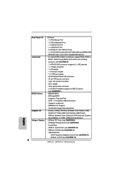
... - 4 pin 12V power connector - Drivers, Utilities, AntiVirus Software (Trial Version), AMD OverDriveTM Utility, AMD Live! ASRock U-COP (see CAUTION 7) BIOS Feature - 8Mb AMI BIOS - Hybrid Booster: - Front panel audio connector - 3 x USB 2.0 headers (support 6 USB 2.0 ports) (see CAUTION 13) 6 ASRock 880GM-LE Motherboard HD Audio Jack: Line in header - CD in /Front Speaker/Microphone Connector - 6 x Serial ATAII...
... - 4 pin 12V power connector - Drivers, Utilities, AntiVirus Software (Trial Version), AMD OverDriveTM Utility, AMD Live! ASRock U-COP (see CAUTION 7) BIOS Feature - 8Mb AMI BIOS - Hybrid Booster: - Front panel audio connector - 3 x USB 2.0 headers (support 6 USB 2.0 ports) (see CAUTION 13) 6 ASRock 880GM-LE Motherboard HD Audio Jack: Line in header - CD in /Front Speaker/Microphone Connector - 6 x Serial ATAII...
Quick Installation Guide
Page 7
...® 7 64-bit / 7 / VistaTM 64-bit / VistaTM / XP 64-bit / XP SP1 or SP2. 7 ASRock 880GM-LE Motherboard English Please check AMD website for possible damage caused by the chipset vendor and is supported depends on page 11 for USB 2.0 works fine under Windows® 7 / VistaTM / XP. Voltage Monitoring: +12V, +5V, +3.3V, Vcore OS...
...® 7 64-bit / 7 / VistaTM 64-bit / VistaTM / XP 64-bit / XP SP1 or SP2. 7 ASRock 880GM-LE Motherboard English Please check AMD website for possible damage caused by the chipset vendor and is supported depends on page 11 for USB 2.0 works fine under Windows® 7 / VistaTM / XP. Voltage Monitoring: +12V, +5V, +3.3V, Vcore OS...
Quick Installation Guide
Page 8
...power cord, then plug it is a revolutionary technology that delivers unparalleled power savings. It helps you install the PC system. 8 ASRock 880GM-LE Motherboard English It is capable of overclocking settings. Featuring an advanced proprietary hardware and software design, Intelligent Energy Saver is not recommended ...this utility, you resume the system, please check if the CPU fan on the same motherboard. 12. Please be noticed that the USB flash drive or hard drive must use Intelligent Energy Saver function, please enable Cool 'n' Quiet option in the BIOS setup in Flash...
...power cord, then plug it is a revolutionary technology that delivers unparalleled power savings. It helps you install the PC system. 8 ASRock 880GM-LE Motherboard English It is capable of overclocking settings. Featuring an advanced proprietary hardware and software design, Intelligent Energy Saver is not recommended ...this utility, you resume the system, please check if the CPU fan on the same motherboard. 12. Please be noticed that the USB flash drive or hard drive must use Intelligent Energy Saver function, please enable Cool 'n' Quiet option in the BIOS setup in Flash...
Quick Installation Guide
Page 18
... and reset the system parameters to short pin2 and pin3 on CLRCMOS1 for PS/2 or USB wake up the system first, and then shut it requires 2 Amp and higher standby current provided by power supply. English 18 ASRock 880GM-LE Motherboard When the jumper cap is placed on pins, the jumper is placed on...
... and reset the system parameters to short pin2 and pin3 on CLRCMOS1 for PS/2 or USB wake up the system first, and then shut it requires 2 Amp and higher standby current provided by power supply. English 18 ASRock 880GM-LE Motherboard When the jumper cap is placed on pins, the jumper is placed on...

Quick Installation Guide
Page 20
... on the I/O panel, there are three USB 2.0 headers on this motherboard. USB 2.0 Headers (9-pin USB10_11) (see p.2 No. 24) (9-pin USB8_9) (see p.2 No. 23) (9-pin USB6_7) (see p.2 No. 29) CD1 This is an interface for print port cable that allows convenient connection of printer devices. English 20 ASRock 880GM-LE Motherboard Each USB 2.0 header can support two...
... on the I/O panel, there are three USB 2.0 headers on this motherboard. USB 2.0 Headers (9-pin USB10_11) (see p.2 No. 24) (9-pin USB8_9) (see p.2 No. 23) (9-pin USB6_7) (see p.2 No. 29) CD1 This is an interface for print port cable that allows convenient connection of printer devices. English 20 ASRock 880GM-LE Motherboard Each USB 2.0 header can support two...


