User Manual
Page 3
... 1.4 I/O Panel 13 2 . Contents 1 . Installation 14 Pre-installation Precautions 14 2.1 CPU Installation 15 2.2 Installation of CPU Fan and Heatsink 15 2.3 Installation of Memory Modules (DIMM 16 2.4 Expansion Slots (PCI and PCI Express Slots 17 2.5 Dual Monitor and Surround Display Features 18 2.6 ATITM Hybrid CrossFireXTM Operation Guide 21 2.7 Jumpers Setup 23 2.8 Onboard Headers and...
... 1.4 I/O Panel 13 2 . Contents 1 . Installation 14 Pre-installation Precautions 14 2.1 CPU Installation 15 2.2 Installation of CPU Fan and Heatsink 15 2.3 Installation of Memory Modules (DIMM 16 2.4 Expansion Slots (PCI and PCI Express Slots 17 2.5 Dual Monitor and Surround Display Features 18 2.6 ATITM Hybrid CrossFireXTM Operation Guide 21 2.7 Jumpers Setup 23 2.8 Onboard Headers and...

User Manual
Page 7
... - 1 x Floppy connector - 1 x IR header - 1 x Print port header - 1 x COM port header - Supports Wake-On-LAN - Explorer, AMD Fusion, CyberLink MediaEspresso 6.5 Trial, ASRock Software Suite (CyberLink DVD Suite - HD Audio Jack: Line in header - Supports jumperfree - ACPI 1.1 Compliance Wake Up... - 24 pin ATX power connector - 4 pin 12V power connector - ASRock Instant Flash (see CAUTION 7) - ASRock OC Tuner (see CAUTION 9) 7 VCCM, NB Voltage Multi-adjustment - Supports "Plug and Play" - LAN Rear Panel I /O Panel - 1 x PS/2 Mouse Port - 1 x PS/2 Keyboard Port ...
... - 1 x Floppy connector - 1 x IR header - 1 x Print port header - 1 x COM port header - Supports Wake-On-LAN - Explorer, AMD Fusion, CyberLink MediaEspresso 6.5 Trial, ASRock Software Suite (CyberLink DVD Suite - HD Audio Jack: Line in header - Supports jumperfree - ACPI 1.1 Compliance Wake Up... - 24 pin ATX power connector - 4 pin 12V power connector - ASRock Instant Flash (see CAUTION 7) - ASRock OC Tuner (see CAUTION 9) 7 VCCM, NB Voltage Multi-adjustment - Supports "Plug and Play" - LAN Rear Panel I /O Panel - 1 x PS/2 Mouse Port - 1 x PS/2 Keyboard Port ...
User Manual
Page 12
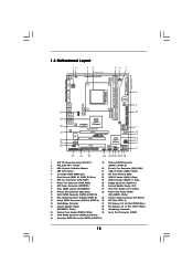
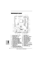
...Connector (FLOPPY1) 8 ATX Power Connector (ATXPWR1) 26 Infrared Module Header (IR1) 9 Clear CMOS Jumper (CLRCMOS1) 27 Print Port Header (LPT1, White) 10 Primary IDE Connector (IDE1, Blue) 28 Front Panel Audio Header 11 Sixth SATAII Connector (SATAII_6 (PORT 5)) (HD_AUDIO1, White) ... 1 HD_AUDIO1 LPT1 1 PCIE1 AMD 880G Chipset Hybrid CrossFire PCIE2 880GM-LE FX PWR_FAN1 IDE1 SATAII_4 SATAII_5 SATAII_6 (PORT 3) (PORT 4) (PORT 5) RoHS PCI1 IR1 1 FLOPPY1 PCI2 USB10_11 1 AMD SB710 Chipset SPEAKER1 1 PLED PWRBTN PANEL 1 1 HDLED RESET 8Mb BIOS USB8_9 1 CHA_FAN1 USB6_7 1 SATAII_1...
...Connector (FLOPPY1) 8 ATX Power Connector (ATXPWR1) 26 Infrared Module Header (IR1) 9 Clear CMOS Jumper (CLRCMOS1) 27 Print Port Header (LPT1, White) 10 Primary IDE Connector (IDE1, Blue) 28 Front Panel Audio Header 11 Sixth SATAII Connector (SATAII_6 (PORT 5)) (HD_AUDIO1, White) ... 1 HD_AUDIO1 LPT1 1 PCIE1 AMD 880G Chipset Hybrid CrossFire PCIE2 880GM-LE FX PWR_FAN1 IDE1 SATAII_4 SATAII_5 SATAII_6 (PORT 3) (PORT 4) (PORT 5) RoHS PCI1 IR1 1 FLOPPY1 PCI2 USB10_11 1 AMD SB710 Chipset SPEAKER1 1 PLED PWRBTN PANEL 1 1 HDLED RESET 8Mb BIOS USB8_9 1 CHA_FAN1 USB6_7 1 SATAII_1...
User Manual
Page 13
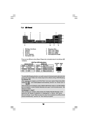
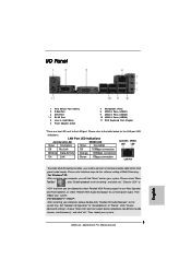
... your system. Then reboot your system. 13 Set "Speaker Configuration" to the LAN port. Please refer to use front panel audio. Click "Device advanced settings", choose "Make front and rear output devices playbacks two different audio streams simultaneously", and click... Link Green 1Gbps connection LAN Port To enable Multi-Streaming function, you are two LED next to "Quadraphonic" or "Stereo". Please refer to the front panel audio header. 1.4 I/O Panel 1 2 3 4 5 6 7 11 10 9 8 1 PS/2 Mouse Port (Green) 2 D-Sub Port 3 DVI-D Port * 4 RJ-45 Port 5 Line In (...
... your system. Then reboot your system. 13 Set "Speaker Configuration" to the LAN port. Please refer to use front panel audio. Click "Device advanced settings", choose "Make front and rear output devices playbacks two different audio streams simultaneously", and click... Link Green 1Gbps connection LAN Port To enable Multi-Streaming function, you are two LED next to "Quadraphonic" or "Stereo". Please refer to the front panel audio header. 1.4 I/O Panel 1 2 3 4 5 6 7 11 10 9 8 1 PS/2 Mouse Port (Green) 2 D-Sub Port 3 DVI-D Port * 4 RJ-45 Port 5 Line In (...

User Manual
Page 25
... AFD# ERROR# PINIT# SLIN# GND 1 SPD7 SPD6 ACK# SPD5 BUSY SPD4 PE SPD3 SLCT SPD2 SPD1 SPD0 STB# Besides six default USB 2.0 ports on the I/O panel, there are three USB 2.0 headers on this motherboard. This is an interface for print port cable that allows convenient connection of printer devices. Each USB...
... AFD# ERROR# PINIT# SLIN# GND 1 SPD7 SPD6 ACK# SPD5 BUSY SPD4 PE SPD3 SLCT SPD2 SPD1 SPD0 STB# Besides six default USB 2.0 ports on the I/O panel, there are three USB 2.0 headers on this motherboard. This is an interface for print port cable that allows convenient connection of printer devices. Each USB...

User Manual
Page 26
.... 26 If you want to MIC2_L. Connect Ground (GND) to function correctly. Enter Windows system. G. Click "Set Default Device" to the front panel audio header as the default record device. System Panel Header (9-pin PANEL1) (see p.12, No. 28) GND PRESENCE# MIC_RET OUT_RET 1 OUT2_L J_SENSE OUT2_R MIC2_R MIC2_L This is an interface for the...
.... 26 If you want to MIC2_L. Connect Ground (GND) to function correctly. Enter Windows system. G. Click "Set Default Device" to the front panel audio header as the default record device. System Panel Header (9-pin PANEL1) (see p.12, No. 28) GND PRESENCE# MIC_RET OUT_RET 1 OUT2_L J_SENSE OUT2_R MIC2_R MIC2_L This is an interface for the...
Quick Installation Guide
Page 2
... DDR3 DIMM Slots 22 SPI Flash Memory (8Mb) (Dual Channel: DDR3_A1, DDR3_B1; White) (SPEAKER 1, White) 33 Northbridge Controller 16 System Panel Header (PANEL1, White) 34 Serial Port Connector (COM1) 17 Third SATAII Connector (SATAII_3 (PORT 2)) 18 Secondary SATAII Connector (SATAII_2 (PORT 1)) 2 ASRock 880GM-LE FX Motherboard Blue) 15 Chassis Speaker Header 32 PCI Express 2.0 x1 Slot (PCIE1;
... DDR3 DIMM Slots 22 SPI Flash Memory (8Mb) (Dual Channel: DDR3_A1, DDR3_B1; White) (SPEAKER 1, White) 33 Northbridge Controller 16 System Panel Header (PANEL1, White) 34 Serial Port Connector (COM1) 17 Third SATAII Connector (SATAII_3 (PORT 2)) 18 Secondary SATAII Connector (SATAII_2 (PORT 1)) 2 ASRock 880GM-LE FX Motherboard Blue) 15 Chassis Speaker Header 32 PCI Express 2.0 x1 Slot (PCIE1;
Quick Installation Guide
Page 3
..."Enable playback multi-streaming", and click "ok". Then reboot your system. 3 ASRock 880GM-LE FX Motherboard English Click "Device advanced settings", choose "Make front and rear output devices playbacks two different audio streams simultaneously", and click "ok". I/O Panel 1 PS/2 Mouse Port (Green) 2 D-Sub Port 3 DVI-D Port * ...Audio 2nd output" to below for the software setting of Multi-Streaming. Set "Speaker Configuration" to the front panel audio header. Then reboot your system. LAN Port LED Indications Activity/Link LED SPEED LED Status Description Status Description ACT/...
..."Enable playback multi-streaming", and click "ok". Then reboot your system. 3 ASRock 880GM-LE FX Motherboard English Click "Device advanced settings", choose "Make front and rear output devices playbacks two different audio streams simultaneously", and click "ok". I/O Panel 1 PS/2 Mouse Port (Green) 2 D-Sub Port 3 DVI-D Port * ...Audio 2nd output" to below for the software setting of Multi-Streaming. Set "Speaker Configuration" to the front panel audio header. Then reboot your system. LAN Port LED Indications Activity/Link LED SPEED LED Status Description Status Description ACT/...
Quick Installation Guide
Page 6
..." functions (see CAUTION 9) ASRock 880GM-LE FX Motherboard Supports "Plug and Play" - ASRock MAGIX Multimedia Suite OEM) - CPU/Chassis/Power FAN connector - 24 pin ATX power connector - 4 pin 12V power connector - ACPI 1.1 Compliance Wake Up Events - ASRock Instant Boot - Realtek RTL8111DL - Supports PXE I /O Connector BIOS Feature Support CD Unique Feature 6 - Front panel audio connector - 3 x USB 2.0 headers (support 6 USB...
..." functions (see CAUTION 9) ASRock 880GM-LE FX Motherboard Supports "Plug and Play" - ASRock MAGIX Multimedia Suite OEM) - CPU/Chassis/Power FAN connector - 24 pin ATX power connector - 4 pin 12V power connector - ACPI 1.1 Compliance Wake Up Events - ASRock Instant Boot - Realtek RTL8111DL - Supports PXE I /O Connector BIOS Feature Support CD Unique Feature 6 - Front panel audio connector - 3 x USB 2.0 headers (support 6 USB...

Quick Installation Guide
Page 22
... ports. English 22 ASRock 880GM-LE FX Motherboard This connector allows you to receive stereo audio input from sound sources such as a CD-ROM, DVD-ROM, TV tuner card, or MPEG card. This header supports an optional wireless transmitting and receiving infrared module. Print Port Header (25-pin LPT1)... No. 26) Internal Audio Connectors (4-pin CD1) (CD1: see p.2 No. 21) Besides six default USB 2.0 ports on the I/O panel, there are three USB 2.0 headers on this motherboard. USB 2.0 Headers (9-pin USB10_11) (see p.2 No. 24) (9-pin USB8_9) (see p.2 No. 23) (9-pin USB6_7) (see p.2 No. 29) ...
... ports. English 22 ASRock 880GM-LE FX Motherboard This connector allows you to receive stereo audio input from sound sources such as a CD-ROM, DVD-ROM, TV tuner card, or MPEG card. This header supports an optional wireless transmitting and receiving infrared module. Print Port Header (25-pin LPT1)... No. 26) Internal Audio Connectors (4-pin CD1) (CD1: see p.2 No. 21) Besides six default USB 2.0 ports on the I/O panel, there are three USB 2.0 headers on this motherboard. USB 2.0 Headers (9-pin USB10_11) (see p.2 No. 24) (9-pin USB8_9) (see p.2 No. 23) (9-pin USB6_7) (see p.2 No. 29) ...

Quick Installation Guide
Page 23
...device. Click "Set Default Device" to enter Realtek HD Audio Manager. System Panel Header (9-pin PANEL1) (see p.2, No. 28) This is an interface for the front panel audio cable that allows convenient connection and control of "Playback" portion. If ...panel. Connect Audio_R (RIN) to OUT2_R and Audio_L (LIN) to the "Front Mic" Tab in "Front Mic" of audio devices. 1. F. Enter Windows system. Front Panel Audio Header (9-pin HD_AUDIO1) (see p.2 No. 16) This header accommodates several system front panel functions. 23 ASRock 880GM-LE FX Motherboard English D. Set the Front Panel...
...device. Click "Set Default Device" to enter Realtek HD Audio Manager. System Panel Header (9-pin PANEL1) (see p.2, No. 28) This is an interface for the front panel audio cable that allows convenient connection and control of "Playback" portion. If ...panel. Connect Audio_R (RIN) to OUT2_R and Audio_L (LIN) to the "Front Mic" Tab in "Front Mic" of audio devices. 1. F. Enter Windows system. Front Panel Audio Header (9-pin HD_AUDIO1) (see p.2 No. 16) This header accommodates several system front panel functions. 23 ASRock 880GM-LE FX Motherboard English D. Set the Front Panel...


