
User Manual
Page 3
... Motherboard Layout 11 1.4 I/O Panel 12 2 . Contents 1 . Installation 13 Pre-installation Precautions 13 2.1 CPU Installation 14 2.2 Installation of CPU Fan and Heatsink 14 2.3 Installation of Memory Modules (DIMM 15 2.4 Expansion Slots (PCI and PCI Express Slots 17 2.5 Surround Display Feature 18 2.6... CrossFireXTM and Quad CrossFireXTM Operation Guide .......... 22 2.7 Jumpers Setup 23 2.8 Onboard Headers and Connectors 24 2.9 Smart Switches 28 2.10 Dr. Debug 29 2.11 Serial ATA3 (SATA3) Hard Disks Installation 32 2.12 ...
... Motherboard Layout 11 1.4 I/O Panel 12 2 . Contents 1 . Installation 13 Pre-installation Precautions 13 2.1 CPU Installation 14 2.2 Installation of CPU Fan and Heatsink 14 2.3 Installation of Memory Modules (DIMM 15 2.4 Expansion Slots (PCI and PCI Express Slots 17 2.5 Surround Display Feature 18 2.6... CrossFireXTM and Quad CrossFireXTM Operation Guide .......... 22 2.7 Jumpers Setup 23 2.8 Onboard Headers and Connectors 24 2.9 Smart Switches 28 2.10 Dr. Debug 29 2.11 Serial ATA3 (SATA3) Hard Disks Installation 32 2.12 ...

User Manual
Page 7
... 1 x eSATAIII Connector - 2 x Ready-to 5Gb/s - 5 x SATA3 6.0Gb/s connectors - 1 x IR header - 1 x COM port header - 1 x IEEE 1394 header - 1 x HDMI_SPDIF header - 1 x Power LED header - Front panel audio connector - 3 x USB 2.0 headers (support 6 USB 2.0 ports) - 1 x Dr. Debug (7-Segment Debug LED) - 1 x Clear CMOS Switch ...1.1 Compliance Wake Up Events - Supports jumperfree - OEM and Trial; ASRock OC Tuner (see CAUTION 8) - Trial) - CPU/Chassis/Power FAN connector - 24 pin ATX power connector - 8 pin 12V power connector - ASRock Instant Flash (see CAUTION 6) - 5 x SATA3 6.0 Gb/s ...
... 1 x eSATAIII Connector - 2 x Ready-to 5Gb/s - 5 x SATA3 6.0Gb/s connectors - 1 x IR header - 1 x COM port header - 1 x IEEE 1394 header - 1 x HDMI_SPDIF header - 1 x Power LED header - Front panel audio connector - 3 x USB 2.0 headers (support 6 USB 2.0 ports) - 1 x Dr. Debug (7-Segment Debug LED) - 1 x Clear CMOS Switch ...1.1 Compliance Wake Up Events - Supports jumperfree - OEM and Trial; ASRock OC Tuner (see CAUTION 8) - Trial) - CPU/Chassis/Power FAN connector - 24 pin ATX power connector - 8 pin 12V power connector - ASRock Instant Flash (see CAUTION 6) - 5 x SATA3 6.0 Gb/s ...
User Manual
Page 11
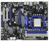
...; White) 31 Serial Port Connector (COM1) 10 Chassis Fan Connector (CHA_FAN1) 32 Infrared Module Header (IR1) 11 ATX Power Connector (ATXPWR1) 33 HDMI_SPDIF Header 12 Chassis Fan Connector (CHA_FAN2) (HDMI_SPDIF1, White) 13 Chassis Fan Connector (CHA_FAN3) 34 PCI Slots (PCI1-2) 14 Northbridge ...USB1 NEC MPD720200 LAN PHY AUDIO CODEC HD_AUDIO1 1 Super I/O HDMI_SPDIF1 1 IR1 1 CHA_FAN3 CHA_FAN2 AMD 870 Chipset PCIE1 Six-Core CPU Ready PCIE2 PCI Express 2.0 870 Extreme3 NEC USB 3.0 SATA3_4_5 PCIE3 CMOS BATTERY 8Mb BIOS PCIE4 AMD SB850 Chipset SATA3_2_3 SATA3_1 PCI1 PCI2 ...
...; White) 31 Serial Port Connector (COM1) 10 Chassis Fan Connector (CHA_FAN1) 32 Infrared Module Header (IR1) 11 ATX Power Connector (ATXPWR1) 33 HDMI_SPDIF Header 12 Chassis Fan Connector (CHA_FAN2) (HDMI_SPDIF1, White) 13 Chassis Fan Connector (CHA_FAN3) 34 PCI Slots (PCI1-2) 14 Northbridge ...USB1 NEC MPD720200 LAN PHY AUDIO CODEC HD_AUDIO1 1 Super I/O HDMI_SPDIF1 1 IR1 1 CHA_FAN3 CHA_FAN2 AMD 870 Chipset PCIE1 Six-Core CPU Ready PCIE2 PCI Express 2.0 870 Extreme3 NEC USB 3.0 SATA3_4_5 PCIE3 CMOS BATTERY 8Mb BIOS PCIE4 AMD SB850 Chipset SATA3_2_3 SATA3_1 PCI1 PCI2 ...
User Manual
Page 26
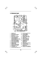
... and match the black wire to the ground pin. Pin 1-3 Connected 3-Pin Fan Installation ATX Power Connector (24-pin ATXPWR1) (see p.11 No. 21) 1 SPEAKER DUMMY DUMMY +5V Please connect the chassis speaker to this header. Chassis Speaker Header (4-pin SPEAKER 1) (see p.11 No. 11) 12 24 Please connect an ATX power supply...
... and match the black wire to the ground pin. Pin 1-3 Connected 3-Pin Fan Installation ATX Power Connector (24-pin ATXPWR1) (see p.11 No. 21) 1 SPEAKER DUMMY DUMMY +5V Please connect the chassis speaker to this header. Chassis Speaker Header (4-pin SPEAKER 1) (see p.11 No. 11) 12 24 Please connect an ATX power supply...


