
RAID Installation Guide
Page 3
...Please insert a floppy diskette into the floppy drive at this moment!) STEP 2: During POST at the following path: .. \ VIA RAID Tool 3 Please select CD-ROM as the boot device. 1.2 Making An SATA Driver Diskette If you want to generate Serial ATA driver diskette [YN]?", press . STEP 3: When you...SATA drivers into the floppy drive. Please refer to the document in the Support CD, "Guide to boot your system. (Do NOT insert any floppy diskette into the floppy drive, and press . WARNING! STEP 1: Insert the ASRock Support CD into your optical drive to VIA RAID Tool", which is located in ...
...Please insert a floppy diskette into the floppy drive at this moment!) STEP 2: During POST at the following path: .. \ VIA RAID Tool 3 Please select CD-ROM as the boot device. 1.2 Making An SATA Driver Diskette If you want to generate Serial ATA driver diskette [YN]?", press . STEP 3: When you...SATA drivers into the floppy drive. Please refer to the document in the Support CD, "Guide to boot your system. (Do NOT insert any floppy diskette into the floppy drive, and press . WARNING! STEP 1: Insert the ASRock Support CD into your optical drive to VIA RAID Tool", which is located in ...

User Manual
Page 4
Software Support 38 4.1 Install Operating System 38 4.2 Support CD Information 38 4.2.1 Running Support CD 38 4.2.2 Drivers Menu 38 4.2.3 Utilities Menu 38 4.2.4 "LGA 775 CPU Installation Live Demo" Program .. 38 4.2.5 Contact Information 38 4 4.
Software Support 38 4.1 Install Operating System 38 4.2 Support CD Information 38 4.2.1 Running Support CD 38 4.2.2 Drivers Menu 38 4.2.3 Utilities Menu 38 4.2.4 "LGA 775 CPU Installation Live Demo" Program .. 38 4.2.5 Contact Information 38 4 4.
User Manual
Page 5
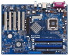
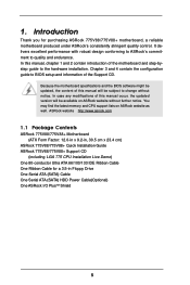
... software might be updated, the content of this manual, chapter 1 and 2 contain introduction of the Support CD. ASRock website http://www.asrock.com 1.1 Package Contents ASRock 775V88/775V88+ Motherboard (ATX Form Factor: 12.0-in x 9.2-in, 30.5 cm x 23.4 cm) ASRock 775V88/775V88+ Quick Installation Guide ASRock 775V88/775V88+ Support CD (including LGA 775 CPU Installation Live Demo) One 80-conductor Ultra ATA 66/100/133...
... software might be updated, the content of this manual, chapter 1 and 2 contain introduction of the Support CD. ASRock website http://www.asrock.com 1.1 Package Contents ASRock 775V88/775V88+ Motherboard (ATX Form Factor: 12.0-in x 9.2-in, 30.5 cm x 23.4 cm) ASRock 775V88/775V88+ Quick Installation Guide ASRock 775V88/775V88+ Support CD (including LGA 775 CPU Installation Live Demo) One 80-conductor Ultra ATA 66/100/133...
User Manual
Page 18
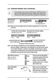
... device on the motherboard. 18 Serial ATA (SATA) Data Cable Either end of your hard disk drive to the primary IDE connector (IDE1, blue) and CD-ROM to optimize compatibility and performance, please connect your IDE device vendor for internal storage devices. Do NOT place jumper caps over the headers and... the red-striped side to 1.5 Gb/s data transfer rate. FDD Connector (33-pin FLOPPY1) (see p.8, No. 10) SATA2 SATA1 These two Serial ATA (SATA) connectors support SATA data cables for the details.
... device on the motherboard. 18 Serial ATA (SATA) Data Cable Either end of your hard disk drive to the primary IDE connector (IDE1, blue) and CD-ROM to optimize compatibility and performance, please connect your IDE device vendor for internal storage devices. Do NOT place jumper caps over the headers and... the red-striped side to 1.5 Gb/s data transfer rate. FDD Connector (33-pin FLOPPY1) (see p.8, No. 10) SATA2 SATA1 These two Serial ATA (SATA) connectors support SATA data cables for the details.

User Manual
Page 19
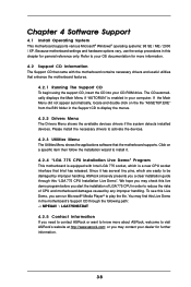
... AUDIO1) (see p.8, No. 22) System Panel Header (9-pin PANEL1) (see p.8, No. 23) AUX-R GND GND AUX-L CD-R GND GND CD-L AUX1 CD1 This header supports an optional wireless transmitting and receiving infrared module. Serial ATA (SATA) Power Cable (Optional) connect to the SATA HDD power connector ...+ PLEDPWRBTN# GND 1 DUMMY RESET# GND HDLEDHDLED+ Chassis Speaker Header (4-pin SPEAKER 1) (see p.8, No. 18) USB_PWR P-7 P+7 GND DUMMY 1 GND P+6 P-6 USB_PWR ASRock I/O PlusTM provides you to the power connector of SATA power cable to receive stereo audio input from sound sources such as...
... AUDIO1) (see p.8, No. 22) System Panel Header (9-pin PANEL1) (see p.8, No. 23) AUX-R GND GND AUX-L CD-R GND GND CD-L AUX1 CD1 This header supports an optional wireless transmitting and receiving infrared module. Serial ATA (SATA) Power Cable (Optional) connect to the SATA HDD power connector ...+ PLEDPWRBTN# GND 1 DUMMY RESET# GND HDLEDHDLED+ Chassis Speaker Header (4-pin SPEAKER 1) (see p.8, No. 18) USB_PWR P-7 P+7 GND DUMMY 1 GND P+6 P-6 USB_PWR ASRock I/O PlusTM provides you to the power connector of SATA power cable to receive stereo audio input from sound sources such as...

User Manual
Page 22
... to boot your optical drive to SATA Hard Disks Installation and RAID Configuration", which is located in it! STEP 1: Insert the ASRock Support CD into the floppy drive, and press . Before you start to configure the RAID function, you need to set the RAID configuration by using "VIA RAID .... WARNING! Please insert a floppy diskette into your system. (Do NOT insert any floppy diskette into the floppy diskette. Please refer to the document in the Support CD, "Guide to check the installation guide in the folder at the following path: .. \ VIA RAID Tool 22
... to boot your optical drive to SATA Hard Disks Installation and RAID Configuration", which is located in it! STEP 1: Insert the ASRock Support CD into the floppy drive, and press . Before you start to configure the RAID function, you need to set the RAID configuration by using "VIA RAID .... WARNING! Please insert a floppy diskette into your system. (Do NOT insert any floppy diskette into the floppy diskette. Please refer to the document in the Support CD, "Guide to check the installation guide in the folder at the following path: .. \ VIA RAID Tool 22
User Manual
Page 38
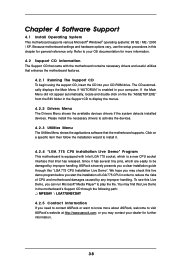
...motherboard is a new CPU socket interface that enhance the motherboard features. 4.2.1 Running The Support CD To begin using the support CD, insert the CD into your OS documentation for more about ASRock, welcome to display the menus. 4.2.2 Drivers Menu The Drivers Menu shows the available devices... drivers if the system detects installed devices. or you need to contact ASRock or want to know more information. 4.2 Support CD Information The Support CD that came with Intel LGA 775 socket, which is equipped with the motherboard contains necessary drivers and...
...motherboard is a new CPU socket interface that enhance the motherboard features. 4.2.1 Running The Support CD To begin using the support CD, insert the CD into your OS documentation for more about ASRock, welcome to display the menus. 4.2.2 Drivers Menu The Drivers Menu shows the available devices... drivers if the system detects installed devices. or you need to contact ASRock or want to know more information. 4.2 Support CD Information The Support CD that came with Intel LGA 775 socket, which is equipped with the motherboard contains necessary drivers and...
Quick Installation Guide
Page 4
... and step-bystep installation guide. This Quick Installation Guide contains introduction of this manual will be available on ASRock website as well. Introduction Thank you for a 3.5-in , 30.5 cm x 23.4 cm) ASRock 775V88/775V88+ Quick Installation Guide ASRock 775V88/775V88+ Support CD (including LGA 775 CPU Installation Live Demo) One 80-conductor Ultra ATA 66/100/133 IDE Ribbon...
... and step-bystep installation guide. This Quick Installation Guide contains introduction of this manual will be available on ASRock website as well. Introduction Thank you for a 3.5-in , 30.5 cm x 23.4 cm) ASRock 775V88/775V88+ Quick Installation Guide ASRock 775V88/775V88+ Support CD (including LGA 775 CPU Installation Live Demo) One 80-conductor Ultra ATA 66/100/133 IDE Ribbon...
Quick Installation Guide
Page 6
... than the recommended CPU bus frequencies may cause the instability of "Hyper Threading Technology", please check page 27 in the support CD. 2. English 6 ASRock 775V88/775V88+ Motherboard While CPU overheat is not recommended to read the installation guide of this motherboard offers stepless control, it back ... fan on the AGP slot of memory modules on page 11 for proper installation. 3. ASRock I/O PlusTM: 1 PS/2 mouse port, 1 PS/2 keyboard port, 1 serial port: COM1, 1 parallel port: ECP/EPP support, 6 ready-to spray thermal grease between the CPU and the heatsink when you install ...
... than the recommended CPU bus frequencies may cause the instability of "Hyper Threading Technology", please check page 27 in the support CD. 2. English 6 ASRock 775V88/775V88+ Motherboard While CPU overheat is not recommended to read the installation guide of this motherboard offers stepless control, it back ... fan on the AGP slot of memory modules on page 11 for proper installation. 3. ASRock I/O PlusTM: 1 PS/2 mouse port, 1 PS/2 keyboard port, 1 serial port: COM1, 1 parallel port: ECP/EPP support, 6 ready-to spray thermal grease between the CPU and the heatsink when you install ...
Quick Installation Guide
Page 15
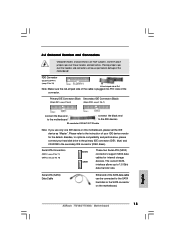
...No. 11) (SATA2: see p.2 No. 10) SATA2 SATA1 These two Serial ATA (SATA) connectors support SATA data cables for the details. FDD Connector (33-pin FLOPPY1) (see p.2 No. 7) connect the...the motherboard. Please refer to the secondary IDE connector (IDE2, black). English 15 ASRock 775V88/775V88+ Motherboard Besides, to optimize compatibility and performance, please connect your hard disk drive to the primary IDE ...connector (IDE1, blue) and CD-ROM to the instruction of the connector. Do NOT place jumper caps over the headers...
...No. 11) (SATA2: see p.2 No. 10) SATA2 SATA1 These two Serial ATA (SATA) connectors support SATA data cables for the details. FDD Connector (33-pin FLOPPY1) (see p.2 No. 7) connect the...the motherboard. Please refer to the secondary IDE connector (IDE2, black). English 15 ASRock 775V88/775V88+ Motherboard Besides, to optimize compatibility and performance, please connect your hard disk drive to the primary IDE ...connector (IDE1, blue) and CD-ROM to the instruction of the connector. Do NOT place jumper caps over the headers...
Quick Installation Guide
Page 16
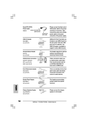
...CD-ROM, DVD-ROM, TV tuner card, or MPEG card. If the rear USB ports are not sufficient, this header. Front Panel Audio Header (9-pin AUDIO1) (see p.2, No. 23) AUX1 CD1 These connectors allow you 6 ready-to-use USB 2.0 ports on the drive. English 16 ASRock 775V88/775V88...) (CD1: see p.2, No. 20) (AUX1: see p.2, No. 22) This is available to support 2 extra USB 2.0 ports. Chassis Speaker Header (4-pin SPEAKER 1) (see p.2, No. 26) This header supports an optional wireless transmitting and receiving infrared module. Serial ATA (SATA) Power Cable (Optional) connect to the...
...CD-ROM, DVD-ROM, TV tuner card, or MPEG card. If the rear USB ports are not sufficient, this header. Front Panel Audio Header (9-pin AUDIO1) (see p.2, No. 23) AUX1 CD1 These connectors allow you 6 ready-to-use USB 2.0 ports on the drive. English 16 ASRock 775V88/775V88...) (CD1: see p.2, No. 20) (AUX1: see p.2, No. 22) This is available to support 2 extra USB 2.0 ports. Chassis Speaker Header (4-pin SPEAKER 1) (see p.2, No. 26) This header supports an optional wireless transmitting and receiving infrared module. Serial ATA (SATA) Power Cable (Optional) connect to the...
Quick Installation Guide
Page 19
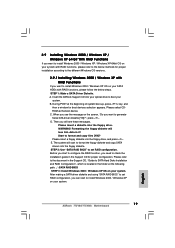
...function, you want to generate Serial ATA driver diskette [YN]?", press . STEP 1: Make a SATA Driver Diskette. A. Insert the ASRock Support CD into the floppy diskette. C. Please insert a floppy diskette into the floppy drive. Please select CDROM as the boot device. E. During... to the document in the Support CD, "Guide to SATA Hard Disks Installation and RAID Configuration", which is located in it! Start to set RAID configuration. WARNING! Before you start to install Windows 2000 / Windows XP on your system. 19 ASRock 775V88/775V88+ Motherboard English B. 2.9 Installing...
...function, you want to generate Serial ATA driver diskette [YN]?", press . STEP 1: Make a SATA Driver Diskette. A. Insert the ASRock Support CD into the floppy diskette. C. Please insert a floppy diskette into the floppy drive. Please select CDROM as the boot device. E. During... to the document in the Support CD, "Guide to SATA Hard Disks Installation and RAID Configuration", which is located in it! Start to set RAID configuration. WARNING! Before you start to install Windows 2000 / Windows XP on your system. 19 ASRock 775V88/775V88+ Motherboard English B. 2.9 Installing...

Quick Installation Guide
Page 20
... at the following path in Windows environment, please install SATA drivers from the Support CD again so that "VIA RAID Tool" will be installed to your system as well. 20 ASRock 775V88/775V88+ Motherboard English Please refer to the document in the Support CD, "Guide to SATA Hard Disks Installation and RAID Configuration", which is located in...
... at the following path in Windows environment, please install SATA drivers from the Support CD again so that "VIA RAID Tool" will be installed to your system as well. 20 ASRock 775V88/775V88+ Motherboard English Please refer to the document in the Support CD, "Guide to SATA Hard Disks Installation and RAID Configuration", which is located in...
Quick Installation Guide
Page 22
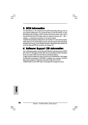
...click on the motherboard stores BIOS Setup Utility. The BIOS Setup program is designed to display the menus. 22 ASRock 775V88/775V88+ Motherboard English Software Support CD information This motherboard supports various Microsoft® Windows® operating systems: 98 SE/ ME / 2000 / XP. otherwise, POST continues...its various sub-menus and to enter BIOS Setup utility; 3. It is enabled in the Support CD to be user-friendly. To begin using the Support CD, insert the CD into your computer. It will enhance motherboard features. BIOS Information The Flash Memory on the file...
...click on the motherboard stores BIOS Setup Utility. The BIOS Setup program is designed to display the menus. 22 ASRock 775V88/775V88+ Motherboard English Software Support CD information This motherboard supports various Microsoft® Windows® operating systems: 98 SE/ ME / 2000 / XP. otherwise, POST continues...its various sub-menus and to enter BIOS Setup utility; 3. It is enabled in the Support CD to be user-friendly. To begin using the Support CD, insert the CD into your computer. It will enhance motherboard features. BIOS Information The Flash Memory on the file...

User Manual
Page 4
Software Support 38 4.1 Install Operating System 38 4.2 Support CD Information 38 4.2.1 Running Support CD 38 4.2.2 Drivers Menu 38 4.2.3 Utilities Menu 38 4.2.4 "LGA 775 CPU Installation Live Demo" Program .. 38 4.2.5 Contact Information 38 4 4.
Software Support 38 4.1 Install Operating System 38 4.2 Support CD Information 38 4.2.1 Running Support CD 38 4.2.2 Drivers Menu 38 4.2.3 Utilities Menu 38 4.2.4 "LGA 775 CPU Installation Live Demo" Program .. 38 4.2.5 Contact Information 38 4 4.

User Manual
Page 5
...-bystep guide to BIOS setup and information of this manual occur, the updated version will be available on ASRock website as well. Introduction Thank you for a 3.5-in , 30.5 cm x 23.4 cm) ASRock 775V88 Quick Installation Guide ASRock 775V88 Support CD (including LGA 775 CPU Installation Live Demo) One 80-conductor Ultra ATA 66/100/133 IDE Ribbon...
...-bystep guide to BIOS setup and information of this manual occur, the updated version will be available on ASRock website as well. Introduction Thank you for a 3.5-in , 30.5 cm x 23.4 cm) ASRock 775V88 Quick Installation Guide ASRock 775V88 Support CD (including LGA 775 CPU Installation Live Demo) One 80-conductor Ultra ATA 66/100/133 IDE Ribbon...

User Manual
Page 18
... ATA Connectors (SATA1: see p.8, No. 11) (SATA2: see p.8, No. 10) SATA2 SATA1 These two Serial ATA (SATA) connectors support SATA data cables for the details. Do NOT place jumper caps over the headers and connectors will cause permanent damage of the connector. Please refer...the IDE device as "Master". Serial ATA (SATA) Data Cable Either end of your hard disk drive to the primary IDE connector (IDE1, blue) and CD-ROM to 1.5 Gb/s data transfer rate. Besides, to optimize compatibility and performance, please connect your IDE device vendor for internal storage devices. The current ...
... ATA Connectors (SATA1: see p.8, No. 11) (SATA2: see p.8, No. 10) SATA2 SATA1 These two Serial ATA (SATA) connectors support SATA data cables for the details. Do NOT place jumper caps over the headers and connectors will cause permanent damage of the connector. Please refer...the IDE device as "Master". Serial ATA (SATA) Data Cable Either end of your hard disk drive to the primary IDE connector (IDE1, blue) and CD-ROM to 1.5 Gb/s data transfer rate. Besides, to optimize compatibility and performance, please connect your IDE device vendor for internal storage devices. The current ...

User Manual
Page 19
...(9-pin AUDIO1) (see p.8, No. 22) System Panel Header (9-pin PANEL1) (see p.8, No. 23) AUX-R GND GND AUX-L CD-R GND GND CD-L AUX1 CD1 This header supports an optional wireless transmitting and receiving infrared module. USB 2.0 Header (9-pin USB67) (see p.8, No. 16) 1 SPEAKER DUMMY DUMMY ... Speaker Header (4-pin SPEAKER 1) (see p.8, No. 18) USB_PWR P-7 P+7 GND DUMMY 1 GND P+6 P-6 USB_PWR ASRock I/O PlusTM provides you to receive stereo audio input from sound sources such as a CD-ROM, DVD-ROM, TV tuner card, or MPEG card. Infrared Module Header (5-pin IR1) IRTX +5V DUMMY (see...
...(9-pin AUDIO1) (see p.8, No. 22) System Panel Header (9-pin PANEL1) (see p.8, No. 23) AUX-R GND GND AUX-L CD-R GND GND CD-L AUX1 CD1 This header supports an optional wireless transmitting and receiving infrared module. USB 2.0 Header (9-pin USB67) (see p.8, No. 16) 1 SPEAKER DUMMY DUMMY ... Speaker Header (4-pin SPEAKER 1) (see p.8, No. 18) USB_PWR P-7 P+7 GND DUMMY 1 GND P+6 P-6 USB_PWR ASRock I/O PlusTM provides you to receive stereo audio input from sound sources such as a CD-ROM, DVD-ROM, TV tuner card, or MPEG card. Infrared Module Header (5-pin IR1) IRTX +5V DUMMY (see...

User Manual
Page 22
STEP 1: Insert the ASRock Support CD into your optical drive to boot your system. (Do NOT insert any floppy diskette...or you may start to configure the RAID function, you install the OS. Please refer to the document in the Support CD, "Guide to SATA Hard Disks Installation and RAID Configuration", which is located in the folder at the beginning of... copy SATA drivers into the floppy diskette. Please refer to the document in the Support CD, "Guide to VIA RAID Tool", which is located in the Support CD for boot devices selection appears. 2.9 Making An SATA Driver Diskette If you want ...
STEP 1: Insert the ASRock Support CD into your optical drive to boot your system. (Do NOT insert any floppy diskette...or you may start to configure the RAID function, you install the OS. Please refer to the document in the Support CD, "Guide to SATA Hard Disks Installation and RAID Configuration", which is located in the folder at the beginning of... copy SATA drivers into the floppy diskette. Please refer to the document in the Support CD, "Guide to VIA RAID Tool", which is located in the Support CD for boot devices selection appears. 2.9 Making An SATA Driver Diskette If you want ...
User Manual
Page 38
... displays the Main Menu if "AUTORUN" is a new CPU socket interface that enhance the motherboard features. 4.2.1 Running The Support CD To begin using the support CD, insert the CD into your dealer for more about ASRock, welcome to install it has several tiny pins, whcih are easily to be damaged by any improper handling. Since it...
... displays the Main Menu if "AUTORUN" is a new CPU socket interface that enhance the motherboard features. 4.2.1 Running The Support CD To begin using the support CD, insert the CD into your dealer for more about ASRock, welcome to install it has several tiny pins, whcih are easily to be damaged by any improper handling. Since it...


