
User Manual
Page 12
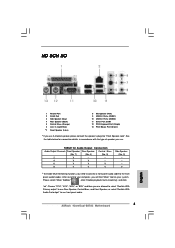
...) 10 USB 2.0 Ports (USB23) 11 Serial Port: COM1 12 PS/2 Keyboard Port (Purple) 13 PS/2 Mouse Port (Green) * If you use front panel audio. 12 See the table below for Audio Output Connection Audio Output Channels Front Speaker Rear Speaker Central / Bass (No. 7) (No. 4) (No. 5) 2 V -- -- 4 V V -- 6 V V V 8 V V V Side Speaker (No. 3) ---V * To enable Multi-Streaming function, you use...
...) 10 USB 2.0 Ports (USB23) 11 Serial Port: COM1 12 PS/2 Keyboard Port (Purple) 13 PS/2 Mouse Port (Green) * If you use front panel audio. 12 See the table below for Audio Output Connection Audio Output Channels Front Speaker Rear Speaker Central / Bass (No. 7) (No. 4) (No. 5) 2 V -- -- 4 V V -- 6 V V V 8 V V V Side Speaker (No. 3) ---V * To enable Multi-Streaming function, you use...
User Manual
Page 22
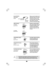
... the front panel audio cable that allows convenient connection and control of audio devices. 1. Then connect the white end of SATA power cable to function correctly. Serial ATA (SATA) Power Cable (Optional) connect to the SATA HDD power connector connect to the power supply Please connect the black ...end of SATA power cable to the power connector on this motherboard. Front Panel Audio Header (9-pin HD_AUDIO1) (see p.11, No. 28)...
... the front panel audio cable that allows convenient connection and control of audio devices. 1. Then connect the white end of SATA power cable to function correctly. Serial ATA (SATA) Power Cable (Optional) connect to the SATA HDD power connector connect to the power supply Please connect the black ...end of SATA power cable to the power connector on this motherboard. Front Panel Audio Header (9-pin HD_AUDIO1) (see p.11, No. 28)...
User Manual
Page 23
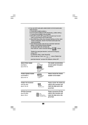
...'97 audio panel. Connect Audio_R (RIN) to OUT2_R and Audio_L (LIN) to this header. C. Enter Advanced Settings, and then select Chipset Configuration. Please connect the chassis speaker to OUT2_L. Chassis Fan Connector (3-pin CHA_FAN1) (see p.11, No. 15) GND +12V CHA_FAN_SPEED Please connect the...DUMMY +5V This header accommodates several system front panel functions. Connect Ground (GND) to connect them for HD audio panel only. You don't need to Ground (GND). Set the Front Panel Control option from [Auto] to enter Realtek HD Audio Manager. Click the icon on the lower ...
...'97 audio panel. Connect Audio_R (RIN) to OUT2_R and Audio_L (LIN) to this header. C. Enter Advanced Settings, and then select Chipset Configuration. Please connect the chassis speaker to OUT2_L. Chassis Fan Connector (3-pin CHA_FAN1) (see p.11, No. 15) GND +12V CHA_FAN_SPEED Please connect the...DUMMY +5V This header accommodates several system front panel functions. Connect Ground (GND) to connect them for HD audio panel only. You don't need to Ground (GND). Set the Front Panel Control option from [Auto] to enter Realtek HD Audio Manager. Click the icon on the lower ...
Quick Installation Guide
Page 3
... "Mixer ToolBox" , click "Enable playback multi-streaming", and click "ok". Choose "2CH", "4CH", "6CH", or "8CH" and then you use. See the table below for Audio Output Connection Audio Output Channels Front Speaker Rear Speaker Central / Bass (No. 7) (No. 4) (No. 5) 2 V -- -- 4 V V -- 6 V V V 8 V V V Side Speaker (No. 3) ---V * To enable Multi-Streaming function, you ... (USB01) 10 USB 2.0 Ports (USB23) 11 Serial Port: COM1 12 PS/2 Keyboard Port (Purple) 13 PS/2 Mouse Port (Green) * If you use front panel audio. 3 ASRock 4CoreDual-SATA2 Motherboard English
... "Mixer ToolBox" , click "Enable playback multi-streaming", and click "ok". Choose "2CH", "4CH", "6CH", or "8CH" and then you use. See the table below for Audio Output Connection Audio Output Channels Front Speaker Rear Speaker Central / Bass (No. 7) (No. 4) (No. 5) 2 V -- -- 4 V V -- 6 V V V 8 V V V Side Speaker (No. 3) ---V * To enable Multi-Streaming function, you ... (USB01) 10 USB 2.0 Ports (USB23) 11 Serial Port: COM1 12 PS/2 Keyboard Port (Purple) 13 PS/2 Mouse Port (Green) * If you use front panel audio. 3 ASRock 4CoreDual-SATA2 Motherboard English
Quick Installation Guide
Page 18
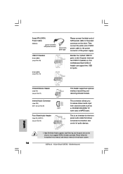
... module. This connector allows you to install your system. 18 ASRock 4CoreDual-SATA2 Motherboard English This is an interface for the front panel audio cable that allows convenient connection and control of the power supply. Then connect the white end of SATA power cable to the power connector ... (SATA) Power Cable (Optional) connect to the SATA HDD power connector connect to the power supply Please connect the black end of SATA power cable to the power connector on this motherboard. High Definition Audio supports Jack Sensing, but the panel wire on the chassis must support HDA...
... module. This connector allows you to install your system. 18 ASRock 4CoreDual-SATA2 Motherboard English This is an interface for the front panel audio cable that allows convenient connection and control of the power supply. Then connect the white end of SATA power cable to the power connector ... (SATA) Power Cable (Optional) connect to the SATA HDD power connector connect to the power supply Please connect the black end of SATA power cable to the power connector on this motherboard. High Definition Audio supports Jack Sensing, but the panel wire on the chassis must support HDA...
Quick Installation Guide
Page 19
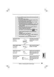
... and Audio_L (LIN) to [Enabled]. D. E. Enter Windows system. System Panel Header (9-pin PANEL1) (see p.2, No. 5) 3 4 Please connect the chassis speaker to the ground pin. 19 ASRock 4CoreDual-SATA2 Motherboard Set the Front Panel Control option from [Auto] to OUT2_L. 2. B. Connect Ground (GND) to enter Realtek HD Audio Manager. F. Please connect the chassis fan cable to this connector and match...
... and Audio_L (LIN) to [Enabled]. D. E. Enter Windows system. System Panel Header (9-pin PANEL1) (see p.2, No. 5) 3 4 Please connect the chassis speaker to the ground pin. 19 ASRock 4CoreDual-SATA2 Motherboard Set the Front Panel Control option from [Auto] to OUT2_L. 2. B. Connect Ground (GND) to enter Realtek HD Audio Manager. F. Please connect the chassis fan cable to this connector and match...

