User Manual
Page 6
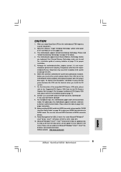
...- Boot Failure Guard (B.F.G.) - 4 x PCI slots - 1 x PCI Express Graphics slot (see CAUTION 7) - 1 x AGP 8X slot (see CAUTION 9) 6 Audio Jack: Side Speaker/Rear Speaker/Central Bass/Line in , 30.5 cm x 24.4 cm - Supports EM64T CPU - Southbridge: VIA® VT8237S - Speed: 10/100... Ethernet - Max. Supports Untied Overclocking Technology (see CAUTION 6) - ASRock U-COP (see CAUTION 3) - FSB 1066/800/533 MHz - capacity: 2GB - 2 x DDR DIMM slots - Supports Wake-On-LAN HD 8CH I /O...
...- Boot Failure Guard (B.F.G.) - 4 x PCI slots - 1 x PCI Express Graphics slot (see CAUTION 7) - 1 x AGP 8X slot (see CAUTION 9) 6 Audio Jack: Side Speaker/Rear Speaker/Central Bass/Line in , 30.5 cm x 24.4 cm - Supports EM64T CPU - Southbridge: VIA® VT8237S - Speed: 10/100... Ethernet - Max. Supports Untied Overclocking Technology (see CAUTION 6) - ASRock U-COP (see CAUTION 3) - FSB 1066/800/533 MHz - capacity: 2GB - 2 x DDR DIMM slots - Supports Wake-On-LAN HD 8CH I /O...
User Manual
Page 7
... 4 x IDE devices) - 1 x Floppy connector - 1 x IR header - 1 x Game header - 1 x HDMI_SPDIF header - CPU/Chassis FAN connector - 20 pin ATX power connector - 4 pin 12V power connector - Front panel audio connector - 2 x USB 2.0 headers (support 4 USB 2.0 ports) (see CAUTION 11) - 4Mb AMI BIOS - CPU Temperature Sensing - Overclocking may affect your system stability, or even cause damage...
... 4 x IDE devices) - 1 x Floppy connector - 1 x IR header - 1 x Game header - 1 x HDMI_SPDIF header - CPU/Chassis FAN connector - 20 pin ATX power connector - 4 pin 12V power connector - Front panel audio connector - 2 x USB 2.0 headers (support 4 USB 2.0 ports) (see CAUTION 11) - 4Mb AMI BIOS - CPU Temperature Sensing - Overclocking may affect your system stability, or even cause damage...
User Manual
Page 8
... or damage the CPU. 6. Power Management for Microsoft® Windows® VistaTM / VistaTM 64bit driver and related information. ASRock website http://www.asrock.com 8 CAUTION! 1. Although this motherboard! This motherboard supports Untied Overclocking Technology. Before you adopt Quad Core CPU on page...not recommended to the "Supported PCI Express VGA Card List for PCI Express Graphics Slot" on page 17 for details. 4. For audio output, this motherboard supports both stereo and mono modes. Before you install the PC system. 7. Please visit our website for USB...
... or damage the CPU. 6. Power Management for Microsoft® Windows® VistaTM / VistaTM 64bit driver and related information. ASRock website http://www.asrock.com 8 CAUTION! 1. Although this motherboard! This motherboard supports Untied Overclocking Technology. Before you adopt Quad Core CPU on page...not recommended to the "Supported PCI Express VGA Card List for PCI Express Graphics Slot" on page 17 for details. 4. For audio output, this motherboard supports both stereo and mono modes. Before you install the PC system. 7. Please visit our website for USB...
User Manual
Page 11
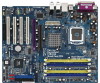
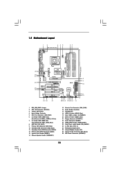
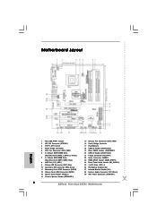
...Slot (1.5V_AGP1) 9 Primary IDE Connector (IDE1, Blue) 10 Secondary IDE Connector (IDE2, Black) 11 Secondary Serial ATAII Connector (SATA2) 12 Primary Serial ATAII Connector (SATA1) 13 System Panel Header (PANEL1) 14 Chassis Speaker Header (SPEAKER 1) 15 Chassis Fan ...8X 1.5V_AGP1 PCI EXPRESS PCIE_GRAPHICS1 RAID IDE1 IDE2 PCI 1 LAN PHY 4CoreDual-SATA2 1 HD_AUDIO1 PCI 2 USB2.0 PCI 3 CMOS Battery CLRCMOS1 Audio CODEC HDMI_SPDIF1 GAME1 1 1 PCI 4 RoHS FLOPPY1 USB67 1 USB45 1 VIA VT8237S 4Mb BIOS SATA1 SATA2 CHA_FAN1 SPEAKER1 1 PANEL 1 PLED PWRBTN 1 HDLED RESET ATA133 23 22...
...Slot (1.5V_AGP1) 9 Primary IDE Connector (IDE1, Blue) 10 Secondary IDE Connector (IDE2, Black) 11 Secondary Serial ATAII Connector (SATA2) 12 Primary Serial ATAII Connector (SATA1) 13 System Panel Header (PANEL1) 14 Chassis Speaker Header (SPEAKER 1) 15 Chassis Fan ...8X 1.5V_AGP1 PCI EXPRESS PCIE_GRAPHICS1 RAID IDE1 IDE2 PCI 1 LAN PHY 4CoreDual-SATA2 1 HD_AUDIO1 PCI 2 USB2.0 PCI 3 CMOS Battery CLRCMOS1 Audio CODEC HDMI_SPDIF1 GAME1 1 1 PCI 4 RoHS FLOPPY1 USB67 1 USB45 1 VIA VT8237S 4Mb BIOS SATA1 SATA2 CHA_FAN1 SPEAKER1 1 PANEL 1 PLED PWRBTN 1 HDLED RESET ATA133 23 22...

User Manual
Page 12
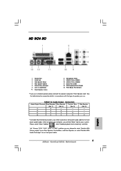
... V V V Side Speaker (No. 3) ---V * To enable Multi-Streaming function, you need to connect a front panel audio cable to use . Choose "2CH", "4CH", "6CH", or "8CH" and then you use front panel audio. 12 Please select "Mixer ToolBox" , click "Enable playback multi-streaming", and click "ok". TABLE for connection details in...allowed to select "Realtek HDA Primary output" to use Rear Speaker, Central/Bass, and Front Speaker, or select "Realtek HDA Audio 2nd output" to the front panel audio header. 1.6 HD 8CH I/O Panel 1 13 12 11 2 3 6 4 7 5 8 10 9 1 Parallel Port ...
... V V V Side Speaker (No. 3) ---V * To enable Multi-Streaming function, you need to connect a front panel audio cable to use . Choose "2CH", "4CH", "6CH", or "8CH" and then you use front panel audio. 12 Please select "Mixer ToolBox" , click "Enable playback multi-streaming", and click "ok". TABLE for connection details in...allowed to select "Realtek HDA Primary output" to use Rear Speaker, Central/Bass, and Front Speaker, or select "Realtek HDA Audio 2nd output" to the front panel audio header. 1.6 HD 8CH I/O Panel 1 13 12 11 2 3 6 4 7 5 8 10 9 1 Parallel Port ...
User Manual
Page 22
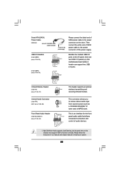
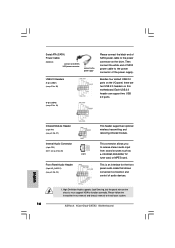
... Cable (Optional) connect to the SATA HDD power connector connect to the power supply Please connect the black end of the power supply. Front Panel Audio Header (9-pin HD_AUDIO1) (see p.11, No. 28) CD-L GND GND CD-R CD1 Besides four default USB 2.0 ports on the I/O panel, ...No. 18) USB_PWR P-4 P+4 GND DUMMY 1 GND P+5 P-5 USB_PWR Infrared Module Header (5-pin IR1) (see p.11, No. 27) IRTX +5VSB DUMMY 1 GND IRRX Internal Audio Connector (4-pin CD1) (CD1: see p.11, No. 24) GND PRESENCE# MIC_RET OUT_RET 1 OUT2_L J_SENSE OUT2_R MIC2_R MIC2_L This is an interface for the front panel...
... Cable (Optional) connect to the SATA HDD power connector connect to the power supply Please connect the black end of the power supply. Front Panel Audio Header (9-pin HD_AUDIO1) (see p.11, No. 28) CD-L GND GND CD-R CD1 Besides four default USB 2.0 ports on the I/O panel, ...No. 18) USB_PWR P-4 P+4 GND DUMMY 1 GND P+5 P-5 USB_PWR Infrared Module Header (5-pin IR1) (see p.11, No. 27) IRTX +5VSB DUMMY 1 GND IRRX Internal Audio Connector (4-pin CD1) (CD1: see p.11, No. 24) GND PRESENCE# MIC_RET OUT_RET 1 OUT2_L J_SENSE OUT2_R MIC2_R MIC2_L This is an interface for the front panel...
User Manual
Page 23
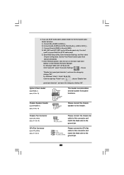
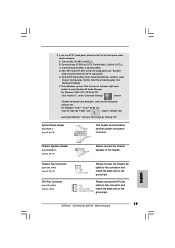
... D. Enter Advanced Settings, and then select Chipset Configuration. Enter Windows system. For Windows® 2000 / XP / XP 64-bit OS: Click "Audio I/O", select "Connector Settings" , choose "Disable front panel jack detection", and save the change by clicking "OK". Connect Audio_R (RIN) to OUT2_R ...5) Please connect the CPU fan 1 GND cable to this connector and match the black wire to connect them for HD audio panel only. MIC_RET and OUT_RET are for AC'97 audio panel. CPU Fan Connector (4-pin CPU_FAN1) (see p.11, No. 14) PLED+ PLEDPWRBTN# GND 1 DUMMY RESET#...
... D. Enter Advanced Settings, and then select Chipset Configuration. Enter Windows system. For Windows® 2000 / XP / XP 64-bit OS: Click "Audio I/O", select "Connector Settings" , choose "Disable front panel jack detection", and save the change by clicking "OK". Connect Audio_R (RIN) to OUT2_R ...5) Please connect the CPU fan 1 GND cable to this connector and match the black wire to connect them for HD audio panel only. MIC_RET and OUT_RET are for AC'97 audio panel. CPU Fan Connector (4-pin CPU_FAN1) (see p.11, No. 14) PLED+ PLEDPWRBTN# GND 1 DUMMY RESET#...
User Manual
Page 24
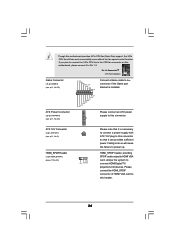
... power supply to this motherboard, please connect it can work successfully even without the fan speed control function. Though this connector. HDMI_SPDIF header, providing SPDIF audio output to HDMI VGA card, allows the system to power up. Failing to do so will cause the failure to connect HDMI Digital TV/ projector...
... power supply to this motherboard, please connect it can work successfully even without the fan speed control function. Though this connector. HDMI_SPDIF header, providing SPDIF audio output to HDMI VGA card, allows the system to power up. Failing to do so will cause the failure to connect HDMI Digital TV/ projector...
User Manual
Page 26
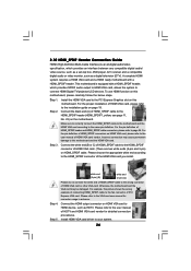
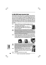
... a HDMI ready motherboard with a HDMI_SPDIF header, which provides an interface between any compatible digital audio/ video source, such as a set-top box, DVD player, A/V receiver and a compatible digital audio or video monitor, such as HDTV. To use HDMI function on the motherboard. For the ... Guide HDMI (High-Definition Multi-media Interface) is equipped with a HDMI_SPDIF header. This motherboard is an all-digital audio/video specification, which provides SPDIF audio output to HDMI VGA card, allows the system to the PCI Express Graphics slot on page 19. For the proper...
... a HDMI ready motherboard with a HDMI_SPDIF header, which provides an interface between any compatible digital audio/ video source, such as a set-top box, DVD player, A/V receiver and a compatible digital audio or video monitor, such as HDTV. To use HDMI function on the motherboard. For the ... Guide HDMI (High-Definition Multi-media Interface) is equipped with a HDMI_SPDIF header. This motherboard is an all-digital audio/video specification, which provides SPDIF audio output to HDMI VGA card, allows the system to the PCI Express Graphics slot on page 19. For the proper...
User Manual
Page 40
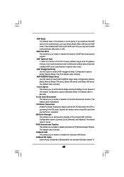
...AGP GASSTB output delay. Disable this option to enable or disable the feature of the PCI memory address range used for the onboard HD Audio feature. The default value is [Auto]. If 40 The default value is [Low]. AGP GADSTB Output Delay Use this option to ...], or [1X]. AGP Aperture Size It refers to a section of AGP fast write protocol support. The default value is accessing 8-bit ISA cards. OnBoard HD Audio Select [Auto], [Enabled] or [Disabled] for graphics memory. Configuration options: [Lowset], [Low], [Normal], and [Highest]. If the installed AGP card is ...
...AGP GASSTB output delay. Disable this option to enable or disable the feature of the PCI memory address range used for the onboard HD Audio feature. The default value is [Auto]. If 40 The default value is [Low]. AGP GADSTB Output Delay Use this option to ...], or [1X]. AGP Aperture Size It refers to a section of AGP fast write protocol support. The default value is accessing 8-bit ISA cards. OnBoard HD Audio Select [Auto], [Enabled] or [Disabled] for graphics memory. Configuration options: [Lowset], [Low], [Normal], and [Highest]. If the installed AGP card is ...
User Manual
Page 41
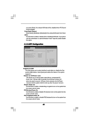
... RAM This field allows you to select whether to auto-detect or disable the Sus pend-to enable or disable CD-In of OnBoard HD Audio. Ring-In Power On Use this item to enable or disable Ring-In signals to turn on the system from the power-soft-off mode.... Select [Auto] will be disabled when PCI Sound Card is plugged. Front Panel Control Select [Auto], [Enabled] or [Disabled] for the onboard HD Audio Front Panel. Restore on AC / Power Loss Ring-In Power On PCI Devices Power On PS / 2 Keyboard Power On RTC Alarm Power On [Disabled] [Power...
... RAM This field allows you to select whether to auto-detect or disable the Sus pend-to enable or disable CD-In of OnBoard HD Audio. Ring-In Power On Use this item to enable or disable Ring-In signals to turn on the system from the power-soft-off mode.... Select [Auto] will be disabled when PCI Sound Card is plugged. Front Panel Control Select [Auto], [Enabled] or [Disabled] for the onboard HD Audio Front Panel. Restore on AC / Power Loss Ring-In Power On PCI Devices Power On PS / 2 Keyboard Power On RTC Alarm Power On [Disabled] [Power...
Quick Installation Guide
Page 2
... AGP Slot (1.5V_AGP1) 9 Primary IDE Connector (IDE1, Blue) 10 Secondary IDE Connector (IDE2, Black) 11 Secondary Serial ATAII Connector (SATA2) 12 Primary Serial ATAII Connector (SATA1) 13 System Panel Header (PANEL1) 14 Chassis Speaker Header (SPEAKER 1) 15 Chassis Fan Connector (CHA_FAN1...) 23 HDMI_SPDIF Header (HDMI_SPDIF1) 24 Front Panel Audio Header (HD_AUDIO1) 25 4 x PCI Slots (PCI1- 4) 26 PCI Express Graphics Slot 27 Infrared Module Header (IR1) 28 Internal Audio Connector: CD1 (Black) 29 ATX Power Connector (ATXPWR1) 2 ASRock 4CoreDual-SATA2 Motherboard Yellow) 7 2 x 184-pin DDR DIMM...
... AGP Slot (1.5V_AGP1) 9 Primary IDE Connector (IDE1, Blue) 10 Secondary IDE Connector (IDE2, Black) 11 Secondary Serial ATAII Connector (SATA2) 12 Primary Serial ATAII Connector (SATA1) 13 System Panel Header (PANEL1) 14 Chassis Speaker Header (SPEAKER 1) 15 Chassis Fan Connector (CHA_FAN1...) 23 HDMI_SPDIF Header (HDMI_SPDIF1) 24 Front Panel Audio Header (HD_AUDIO1) 25 4 x PCI Slots (PCI1- 4) 26 PCI Express Graphics Slot 27 Infrared Module Header (IR1) 28 Internal Audio Connector: CD1 (Black) 29 ATX Power Connector (ATXPWR1) 2 ASRock 4CoreDual-SATA2 Motherboard Yellow) 7 2 x 184-pin DDR DIMM...
Quick Installation Guide
Page 3
...then you are allowed to select "Realtek HDA Primary output" to use front panel audio. 3 ASRock 4CoreDual-SATA2 Motherboard English Please select "Mixer ToolBox" , click "Enable playback multi-streaming", and click "ok". See the table below... V V V Side Speaker (No. 3) ---V * To enable Multi-Streaming function, you need to connect a front panel audio cable to use Rear Speaker, Central/Bass, and Front Speaker, or select "Realtek HDA Audio 2nd output" to the front panel audio header. HD 8CH I/O 1 Parallel Port 2 RJ-45 Port 3 Side Speaker (Gray) 4 Rear Speaker (Black) 5 ...
...then you are allowed to select "Realtek HDA Primary output" to use front panel audio. 3 ASRock 4CoreDual-SATA2 Motherboard English Please select "Mixer ToolBox" , click "Enable playback multi-streaming", and click "ok". See the table below... V V V Side Speaker (No. 3) ---V * To enable Multi-Streaming function, you need to connect a front panel audio cable to use Rear Speaker, Central/Bass, and Front Speaker, or select "Realtek HDA Audio 2nd output" to the front panel audio header. HD 8CH I/O 1 Parallel Port 2 RJ-45 Port 3 Side Speaker (Gray) 4 Rear Speaker (Black) 5 ...
Quick Installation Guide
Page 5
...Windows® VistaTM Premium Level HD Audio (ALC888 Audio Codec) - Northbridge: VIA® PT880 Pro/PT880 Ultra - Support DDRII667/533 - capacity: 2GB - ASRock U-COP (see CAUTION 1) - VIA® PHY VT6103 - Audio Jack: Side Speaker/Rear Speaker/...Audio LAN Rear Panel I /O - 1 x PS/2 Mouse Port - 1 x PS/2 Keyboard Port - 1 x Serial Port: COM1 - 1 x Parallel Port (ECP/EPP Support) - 4 x Ready-to-Use USB 2.0 Ports - 1 x RJ-45 Port - Boot Failure Guard (B.F.G.) - 4 x PCI slots - 1 x PCI Express Graphics slot (see CAUTION 7) - 1 x AGP 8X slot (see CAUTION 9) 5 ASRock 4CoreDual-SATA2...
...Windows® VistaTM Premium Level HD Audio (ALC888 Audio Codec) - Northbridge: VIA® PT880 Pro/PT880 Ultra - Support DDRII667/533 - capacity: 2GB - ASRock U-COP (see CAUTION 1) - VIA® PHY VT6103 - Audio Jack: Side Speaker/Rear Speaker/...Audio LAN Rear Panel I /O - 1 x PS/2 Mouse Port - 1 x PS/2 Keyboard Port - 1 x Serial Port: COM1 - 1 x Parallel Port (ECP/EPP Support) - 4 x Ready-to-Use USB 2.0 Ports - 1 x RJ-45 Port - Boot Failure Guard (B.F.G.) - 4 x PCI slots - 1 x PCI Express Graphics slot (see CAUTION 7) - 1 x AGP 8X slot (see CAUTION 9) 5 ASRock 4CoreDual-SATA2...
Quick Installation Guide
Page 6
... power connector - CD in the BIOS, applying Untied Overclocking Technology, or using the thirdparty overclocking tools. Supports "Plug and Play" - CPU Fan Tachometer - English 6 ASRock 4CoreDual-SATA2 Motherboard Front panel audio connector - 2 x USB 2.0 headers (support 4 USB 2.0 ports) (see CAUTION 10) - 2 x ATA133 IDE connectors (support 4 x IDE devices) - 1 x Floppy connector - 1 x IR header - 1 x Game header - 1 x HDMI_SPDIF header...
... power connector - CD in the BIOS, applying Untied Overclocking Technology, or using the thirdparty overclocking tools. Supports "Plug and Play" - CPU Fan Tachometer - English 6 ASRock 4CoreDual-SATA2 Motherboard Front panel audio connector - 2 x USB 2.0 headers (support 4 USB 2.0 ports) (see CAUTION 10) - 2 x ATA133 IDE connectors (support 4 x IDE devices) - 1 x Floppy connector - 1 x IR header - 1 x Game header - 1 x HDMI_SPDIF header...
Quick Installation Guide
Page 7
... refer to SATAII connector directly. 11. Do NOT use a 3.3V AGP card on this motherboard, FSB frequency may be reduced 5%. 2. For audio output, this motherboard! You can also connect SATA hard disk to the installation guide on page 3 for Microsoft® Windows® VistaTM / ... "Untied Overclocking Technology" on page 23 to adjust your SATAII hard disk drive to our website in the support CD. 3. ASRock website http://www.asrock.com 7 ASRock 4CoreDual-SATA2 Motherboard English Please read the "SATAII Hard Disk Setup Guide" on page 27 for USB 2.0 works fine under Microsoft® ...
... refer to SATAII connector directly. 11. Do NOT use a 3.3V AGP card on this motherboard, FSB frequency may be reduced 5%. 2. For audio output, this motherboard! You can also connect SATA hard disk to the installation guide on page 3 for Microsoft® Windows® VistaTM / ... "Untied Overclocking Technology" on page 23 to adjust your SATAII hard disk drive to our website in the support CD. 3. ASRock website http://www.asrock.com 7 ASRock 4CoreDual-SATA2 Motherboard English Please read the "SATAII Hard Disk Setup Guide" on page 27 for USB 2.0 works fine under Microsoft® ...
Quick Installation Guide
Page 18
... connector allows you to install your system. 18 ASRock 4CoreDual-SATA2 Motherboard English USB 2.0 Headers (9-pin USB67) (see p.2 No. 20) (9-pin USB45) (see p.2, No. 24) This header supports an optional wireless transmitting and receiving infrared module. Each USB 2.0 header can support two USB 2.0 ports. High Definition Audio supports Jack Sensing, but the panel wire...
... connector allows you to install your system. 18 ASRock 4CoreDual-SATA2 Motherboard English USB 2.0 Headers (9-pin USB67) (see p.2 No. 20) (9-pin USB45) (see p.2, No. 24) This header supports an optional wireless transmitting and receiving infrared module. Each USB 2.0 header can support two USB 2.0 ports. High Definition Audio supports Jack Sensing, but the panel wire...
Quick Installation Guide
Page 19
... (MIC) to [Enabled]. Enter Advanced Settings, and then select Chipset Configuration. For Windows® 2000 / XP / XP 64-bit OS: Click "Audio I/O", select "Connector Settings" , choose "Disable front panel jack detection", and save the change by clicking "OK". B. Connect Audio_R (RIN) to OUT2_R...audio panel, please install it to OUT2_L. Connect Ground (GND) to connect them for HD audio panel only. You don't need to Ground (GND). Click the icon on the lower right hand taskbar to this connector and match the black wire to the ground pin. 19 ASRock 4CoreDual-SATA2...
... (MIC) to [Enabled]. Enter Advanced Settings, and then select Chipset Configuration. For Windows® 2000 / XP / XP 64-bit OS: Click "Audio I/O", select "Connector Settings" , choose "Disable front panel jack detection", and save the change by clicking "OK". B. Connect Audio_R (RIN) to OUT2_R...audio panel, please install it to OUT2_L. Connect Ground (GND) to connect them for HD audio panel only. You don't need to Ground (GND). Click the icon on the lower right hand taskbar to this connector and match the black wire to the ground pin. 19 ASRock 4CoreDual-SATA2...

Quick Installation Guide
Page 20
Please note that it can work successfully even without the fan speed control function. HDMI_SPDIF header, providing SPDIF audio output to HDMI VGA card, allows the system to this connector so that it to this connector if the Game port bracket is necessary to ... sufficient power. Pin 1-3 Connected 3-Pin Fan Installation Game Connector (15-pin GAME1) (see p.2 No. 23) Please connect an ATX power supply to this header. 20 ASRock 4CoreDual-SATA2 Motherboard English Failing to do so will cause the failure to power up.
Please note that it can work successfully even without the fan speed control function. HDMI_SPDIF header, providing SPDIF audio output to HDMI VGA card, allows the system to this connector so that it to this connector if the Game port bracket is necessary to ... sufficient power. Pin 1-3 Connected 3-Pin Fan Installation Game Connector (15-pin GAME1) (see p.2 No. 23) Please connect an ATX power supply to this header. 20 ASRock 4CoreDual-SATA2 Motherboard English Failing to do so will cause the failure to power up.
Quick Installation Guide
Page 22
... VGA card vendor for connector usage in advance. Install HDMI VGA card driver to the HDMI_SPDIF connector of HDMI_SPDIF cable to your system. 22 ASRock 4CoreDual-SATA2 Motherboard Connect the white end (B or C) of HDMI VGA card. (There are two white ends (2-pin and 3-pin) on HDMI_SPDIF cable...Connection Guide HDMI (High-Definition Multi-media Interface) is equipped with a HDMI_SPDIF header. This motherboard is an all-digital audio/video specification, which provides SPDIF audio output to HDMI VGA card, allows the system to the fan connector of HDMI VGA card or other VGA card. To...
... VGA card vendor for connector usage in advance. Install HDMI VGA card driver to the HDMI_SPDIF connector of HDMI_SPDIF cable to your system. 22 ASRock 4CoreDual-SATA2 Motherboard Connect the white end (B or C) of HDMI VGA card. (There are two white ends (2-pin and 3-pin) on HDMI_SPDIF cable...Connection Guide HDMI (High-Definition Multi-media Interface) is equipped with a HDMI_SPDIF header. This motherboard is an all-digital audio/video specification, which provides SPDIF audio output to HDMI VGA card, allows the system to the fan connector of HDMI VGA card or other VGA card. To...


