
User Manual
Page 2
...any means, except duplication of documentation by the purchaser for any errors or omissions that may cause undesired operation. ASRock assumes no event shall ASRock, its directors, officers, employees, or agents be liable for any kind, either expressed or implied, including but...of any indirect, special, incidental, or consequential damages (including damages for a particular purpose. With respect to the contents of this motherboard contains Perchlorate, a toxic substance controlled in this manual may or may not be constructed as a commitment by the California Legislature. CALIFORNIA...
...any means, except duplication of documentation by the purchaser for any errors or omissions that may cause undesired operation. ASRock assumes no event shall ASRock, its directors, officers, employees, or agents be liable for any kind, either expressed or implied, including but...of any indirect, special, incidental, or consequential damages (including damages for a particular purpose. With respect to the contents of this motherboard contains Perchlorate, a toxic substance controlled in this manual may or may not be constructed as a commitment by the California Legislature. CALIFORNIA...

User Manual
Page 3
Contents 1 Introduction 5 1.1 Package Contents 5 1.2 Specifications 6 1.3 Minimum Hardware Requirement Table for Windows® VistaTM Premium 2007 and Basic Logo 9 1.4 Motherboard Layout 10 1.5 ASRock 6CH I/O Pro 11 2 Installation 12 2.1 Screw Holes 12 2.2 Pre-installation Precautions 12 2.3 CPU Installation 13 2.4 Installation of Heatsink and CPU fan 15 2.5 Installation of Memory ...
Contents 1 Introduction 5 1.1 Package Contents 5 1.2 Specifications 6 1.3 Minimum Hardware Requirement Table for Windows® VistaTM Premium 2007 and Basic Logo 9 1.4 Motherboard Layout 10 1.5 ASRock 6CH I/O Pro 11 2 Installation 12 2.1 Screw Holes 12 2.2 Pre-installation Precautions 12 2.3 CPU Installation 13 2.4 Installation of Heatsink and CPU fan 15 2.5 Installation of Memory ...

User Manual
Page 5
... occur, the updated version will be updated, the content of the Support CD. www.asrock.com/support/index.asp 1.1 Package Contents ASRock 4Core1600-GLAN Motherboard (ATX Form Factor: 12.0-in x 8.6-in Floppy Drive One Serial ATA (SATA) Data... 21.8 cm) ASRock 4Core1600-GLAN Quick Installation Guide ASRock 4Core1600-GLAN Support CD One 80-conductor Ultra ATA 66/100 IDE Ribbon Cable One Ribbon Cable for purchasing ASRock 4Core1600-GLAN motherboard, a reliable motherboard produced under ASRock's consistently stringent quality control. Because the motherboard specifications and the BIOS...
... occur, the updated version will be updated, the content of the Support CD. www.asrock.com/support/index.asp 1.1 Package Contents ASRock 4Core1600-GLAN Motherboard (ATX Form Factor: 12.0-in x 8.6-in Floppy Drive One Serial ATA (SATA) Data... 21.8 cm) ASRock 4Core1600-GLAN Quick Installation Guide ASRock 4Core1600-GLAN Support CD One 80-conductor Ultra ATA 66/100 IDE Ribbon Cable One Ribbon Cable for purchasing ASRock 4Core1600-GLAN motherboard, a reliable motherboard produced under ASRock's consistently stringent quality control. Because the motherboard specifications and the BIOS...

User Manual
Page 8
...19 for the CPU FSB frequency and its corresponding memory support frequency. You can also connect SATA hard disk to perform over-clocking. Under this motherboard, please read the installation guide of Memory Modules (DIMM)" on page 16 for system usage under Microsoft® Windows® VistaTM 64-bit... / VistaTM / XP 64-bit / XP SP1 or SP2 / 2000 SP4. 8 This motherboard supports Dual Channel Memory Technology. For Windows® XP 64-bit and Windows® VistaTM 64- Before you install the PC system. 10. If you...
...19 for the CPU FSB frequency and its corresponding memory support frequency. You can also connect SATA hard disk to perform over-clocking. Under this motherboard, please read the installation guide of Memory Modules (DIMM)" on page 16 for system usage under Microsoft® Windows® VistaTM 64-bit... / VistaTM / XP 64-bit / XP SP1 or SP2 / 2000 SP4. 8 This motherboard supports Dual Channel Memory Technology. For Windows® XP 64-bit and Windows® VistaTM 64- Before you install the PC system. 10. If you...

User Manual
Page 9
ASRock website http://www.asrock.com 1.3 Minimum Hardware Requirement Table for Windows® VistaTM Premium 2007 and Basic Logo For system integrators and users who purchase this motherboard and plan to -use wireless local area network (WLAN) adapter. CPU Memory VGA Celeron 420 1GB system memory (Premium) 512MB ...Single Channel (Basic) DX9.0 with WDDM Driver with 128bit VGA memory (Premium) with ASRock WiFi-802.11g or WiFi-...
ASRock website http://www.asrock.com 1.3 Minimum Hardware Requirement Table for Windows® VistaTM Premium 2007 and Basic Logo For system integrators and users who purchase this motherboard and plan to -use wireless local area network (WLAN) adapter. CPU Memory VGA Celeron 420 1GB system memory (Premium) 512MB ...Single Channel (Basic) DX9.0 with WDDM Driver with 128bit VGA memory (Premium) with ASRock WiFi-802.11g or WiFi-...

User Manual
Page 10
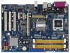
...PCI1 - 3) 29 PCI Express x1 Slot (PCIE3/DE) 30 PCI Express x1 Slot (PCIE2) 31 PCI Express x16 Slot (PCIE1) 32 FD Jumper 10 1.4 Motherboard Layout 1 2 34 56 PS2 Keyboard 1 PS2 Mouse PS2_USB_PWR1 ATX12V1 21.8cm (8.6 in) CPU_FAN1 78 PARALLEL PORT COM1 DDRII_4 (64 bit, 240-pin module) DDRII_3..., 240-pin module) Yorkfield Wolfdale Quad Core CPU DDR2 800 32 31 30 29 28 27 ATXPWR1 Top: LINE IN Center: FRONT Bottom: MIC IN 4Core1600-GLAN Dual Channel USB 2.0 T: USB2 B: USB3 USB 2.0 T: USB0 B: USB1 Top: RJ-45 Intel IDE1 P31/G31 Chipset PCI EXPRESS FD 1 LAN PCIE1 PHY ...
...PCI1 - 3) 29 PCI Express x1 Slot (PCIE3/DE) 30 PCI Express x1 Slot (PCIE2) 31 PCI Express x16 Slot (PCIE1) 32 FD Jumper 10 1.4 Motherboard Layout 1 2 34 56 PS2 Keyboard 1 PS2 Mouse PS2_USB_PWR1 ATX12V1 21.8cm (8.6 in) CPU_FAN1 78 PARALLEL PORT COM1 DDRII_4 (64 bit, 240-pin module) DDRII_3..., 240-pin module) Yorkfield Wolfdale Quad Core CPU DDR2 800 32 31 30 29 28 27 ATXPWR1 Top: LINE IN Center: FRONT Bottom: MIC IN 4Core1600-GLAN Dual Channel USB 2.0 T: USB2 B: USB3 USB 2.0 T: USB0 B: USB1 Top: RJ-45 Intel IDE1 P31/G31 Chipset PCI EXPRESS FD 1 LAN PCIE1 PHY ...

User Manual
Page 12
...ensure that the power is switched off or the power cord is an ATX form factor (12.0" x 8.6", 30.5 x 21.8 cm) motherboard. Do not over-tighten the screws! Unplug the power cord from the power supply. Hold components by the edges and do so may damage...do not touch the ICs. 4. Whenever you install the motherboard, study the configuration of the following precautions before you and damages to motherboard components. 2.1 Screw Holes Place screws into it on the carpet or the like. Chapter 2 Installation 4Core1600-GLAN is detached from the wall socket before installing or removing...
...ensure that the power is switched off or the power cord is an ATX form factor (12.0" x 8.6", 30.5 x 21.8 cm) motherboard. Do not over-tighten the screws! Unplug the power cord from the power supply. Hold components by the edges and do so may damage...do not touch the ICs. 4. Whenever you install the motherboard, study the configuration of the following precautions before you and damages to motherboard components. 2.1 Screw Holes Place screws into it on the carpet or the like. Chapter 2 Installation 4Core1600-GLAN is detached from the wall socket before installing or removing...

User Manual
Page 14
... that the CPU is recommended to use the cap tab to the orient keys. Step 4-2. Step 4. Step 3. This cap must be placed if returning the motherboard for after service.
... that the CPU is recommended to use the cap tab to the orient keys. Step 4-2. Step 4. Step 3. This cap must be placed if returning the motherboard for after service.

User Manual
Page 15
...caps with fan operation or contact other . Step 6. 2.4 Installation of CPU Fan and Heatsink This motherboard is an example to dissipate heat. Please adopt the type of IHS on the motherboard (CPU_FAN1, see page 10, No. 6). For proper installation, please kindly refer to the instruction ...the fastener clockwise, then press down the fasteners without rotating them clockwise, the heatsink cannot be secured on the motherboard. Below is equipped with the motherboard throughholes. Step 3. Ensure fan cables are securely fastened and in good contact with the CPU fan connector on the...
...caps with fan operation or contact other . Step 6. 2.4 Installation of CPU Fan and Heatsink This motherboard is an example to dissipate heat. Please adopt the type of IHS on the motherboard (CPU_FAN1, see page 10, No. 6). For proper installation, please kindly refer to the instruction ...the fastener clockwise, then press down the fasteners without rotating them clockwise, the heatsink cannot be secured on the motherboard. Below is equipped with the motherboard throughholes. Step 3. Ensure fan cables are securely fastened and in good contact with the CPU fan connector on the...

User Manual
Page 16
...DDR2 DIMMs for example, installing a pair of the same color. For dual channel configuration, you to activate the Dual Channel Memory Technology. 3. This motherboard also allows you always need to install a DDR memory module into DDR2 slot; 2.5 Installation of memory modules is NOT installed in the same Dual Channel... (the same brand, speed, size and chip-type) DDR2 DIMM pair in Dual Channel B (DDRII_2 and DDRII_4; If a pair of Memory Modules (DIMM) 4Core1600-GLAN motherboard provides four 240-pin DDR2 (Double Data Rate 2) DIMM slots, and supports Dual Channel Memory Technology.
...DDR2 DIMMs for example, installing a pair of the same color. For dual channel configuration, you to activate the Dual Channel Memory Technology. 3. This motherboard also allows you always need to install a DDR memory module into DDR2 slot; 2.5 Installation of memory modules is NOT installed in the same Dual Channel... (the same brand, speed, size and chip-type) DDR2 DIMM pair in Dual Channel B (DDRII_2 and DDRII_4; If a pair of Memory Modules (DIMM) 4Core1600-GLAN motherboard provides four 240-pin DDR2 (Double Data Rate 2) DIMM slots, and supports Dual Channel Memory Technology.

User Manual
Page 17
... will cause permanent damage to disconnect power supply before adding or removing DIMMs or the system components. Step 3. Installing a DIMM Please make sure to the motherboard and the DIMM if you can install it to any one correct orientation. Unlock a DIMM slot by pressing the retaining clips outward.
... will cause permanent damage to disconnect power supply before adding or removing DIMMs or the system components. Step 3. Installing a DIMM Please make sure to the motherboard and the DIMM if you can install it to any one correct orientation. Unlock a DIMM slot by pressing the retaining clips outward.

User Manual
Page 18
... Express cards with screws. 18 Please read the documentation of the expansion card and make sure that you want to use ASRock DeskExpress function on this motherboard. Keep the screws for PCI Express cards with the slot and press firmly until the card is used for the card ... expansion cards that have the 32-bit PCI interface. Step 3. PCI slots: PCI slots are 3 PCI slots and 3 PCI Express slots on this motherboard, please install ASRock PCIE_DE card on the slot. If you intend to use . Step 4. Installing an expansion card Step 1. Step 2. PCIE slots: PCIE1 (PCIE x16...
... Express cards with screws. 18 Please read the documentation of the expansion card and make sure that you want to use ASRock DeskExpress function on this motherboard. Keep the screws for PCI Express cards with the slot and press firmly until the card is used for the card ... expansion cards that have the 32-bit PCI interface. Step 3. PCI slots: PCI slots are 3 PCI slots and 3 PCI Express slots on this motherboard, please install ASRock PCIE_DE card on the slot. If you intend to use . Step 4. Installing an expansion card Step 1. Step 2. PCIE slots: PCIE1 (PCIE x16...

User Manual
Page 19
...and pin2 are setup. FD Jumper (FD, 3-pin jumper, see p.10 No. 32) 1_2 FD Default Note1: If you use a FSB1600-CPU on this motherboard. Jumper Setting Description PS2_USB_PWR1 (see p.10 No. 10) 2-pin jumper Note: CLRCMOS1 allows you need to adjust the jumpers. Clear CMOS (CLRCMOS1, 2-pin ... Setup The illustration shows how jumpers are "Short" when jumper cap is placed on these 2 pins. When the jumper cap is placed on this motherboard, you to enable +5VSB (standby) for 15 seconds, use a jumper cap to default setup, please turn off the computer and unplug the power...
...and pin2 are setup. FD Jumper (FD, 3-pin jumper, see p.10 No. 32) 1_2 FD Default Note1: If you use a FSB1600-CPU on this motherboard. Jumper Setting Description PS2_USB_PWR1 (see p.10 No. 10) 2-pin jumper Note: CLRCMOS1 allows you need to adjust the jumpers. Clear CMOS (CLRCMOS1, 2-pin ... Setup The illustration shows how jumpers are "Short" when jumper cap is placed on these 2 pins. When the jumper cap is placed on this motherboard, you to enable +5VSB (standby) for 15 seconds, use a jumper cap to default setup, please turn off the computer and unplug the power...

User Manual
Page 20
... cables for the details. Then connect the white end of the connector. The current SATAII interface allows up to the power connector of the motherboard! Placing jumper caps over these headers and connectors. Serial ATAII Connectors (SATAII_1 (Port0): see p.10, No. 17) (SATAII_2 (Port1): ...10, No. 14) (SATAII_4 (Port3): see p.10 No. 23) Pin1 FLOPPY1 the red-striped side to the power connector on this motherboard. Do NOT place jumper caps over the headers and connectors will cause permanent damage of the power supply. 20 2.8 Onboard Headers and Connectors ...
... cables for the details. Then connect the white end of the connector. The current SATAII interface allows up to the power connector of the motherboard! Placing jumper caps over these headers and connectors. Serial ATAII Connectors (SATAII_1 (Port0): see p.10, No. 17) (SATAII_2 (Port1): ...10, No. 14) (SATAII_4 (Port3): see p.10 No. 23) Pin1 FLOPPY1 the red-striped side to the power connector on this motherboard. Do NOT place jumper caps over the headers and connectors will cause permanent damage of the power supply. 20 2.8 Onboard Headers and Connectors ...

User Manual
Page 21
... Hot Plug Detection Header (5-pin IR1) (see p.10 No. 22) IRTX +5VSB Hotplug# 1 GND IRRX This header supports the Hot Plug detection function for ASRock DeskExpress. WiFi/E Header (15-pin WIFI/E) (see p.10 No. 27) USB+5V_2 TXN TXP GND2 PCIE_RST# +3SVB RXN RXP 1 GND1 D0-D0+ PexCLK... P+6 USB_PWR Besides four default USB 2.0 ports on the I/O panel, there are two USB 2.0 headers on this motherboard, this picture for proper installation. It allows you to -use WiFi+AP functin on this motherboard. USB4_5 header can support two USB 2.0 ports, and USB6 header can be used as a CD-ROM, DVD...
... Hot Plug Detection Header (5-pin IR1) (see p.10 No. 22) IRTX +5VSB Hotplug# 1 GND IRRX This header supports the Hot Plug detection function for ASRock DeskExpress. WiFi/E Header (15-pin WIFI/E) (see p.10 No. 27) USB+5V_2 TXN TXP GND2 PCIE_RST# +3SVB RXN RXP 1 GND1 D0-D0+ PexCLK... P+6 USB_PWR Besides four default USB 2.0 ports on the I/O panel, there are two USB 2.0 headers on this motherboard, this picture for proper installation. It allows you to -use WiFi+AP functin on this motherboard. USB4_5 header can support two USB 2.0 ports, and USB6 header can be used as a CD-ROM, DVD...

User Manual
Page 23
...connect the white end (B or C) of HDMI VGA card to connect HDMI Digital TV/ projector/LCD devices. black end B. Though this motherboard provides 4-Pin CPU fan (Quiet Fan) support, the 3-Pin CPU fan still can still work successfully even without the fan speed control ...Please connect an ATX 12V power supply to Pin 1-3. HDMI_SPDIF header, providing SPDIF audio output to HDMI VGA card, allows the system to this motherboard provides 24-pin ATX power connector, 13 1 it to this connector. Please connect the HDMI_SPDIF connector of HDMI_SPDIF cable to the HDMI_SPDIF header ...
...connect the white end (B or C) of HDMI VGA card to connect HDMI Digital TV/ projector/LCD devices. black end B. Though this motherboard provides 4-Pin CPU fan (Quiet Fan) support, the 3-Pin CPU fan still can still work successfully even without the fan speed control ...Please connect an ATX 12V power supply to Pin 1-3. HDMI_SPDIF header, providing SPDIF audio output to HDMI VGA card, allows the system to this motherboard provides 24-pin ATX power connector, 13 1 it to this connector. Please connect the HDMI_SPDIF connector of HDMI_SPDIF cable to the HDMI_SPDIF header ...

User Manual
Page 24
...such as a digital television (DTV). Incorrect connection may be damaged. Please refer to the same pin definition. To use HDMI function on this motherboard and the HDMI VGA card. Install the HDMI VGA card to the• PCI Express Graphics slot on HDMI VGA card, please refer to the...manual of HDMI_SPDIF header and HDMI_SPDIF cable connectors, please refer to your system. 24 Make sure to correctly connect the HDMI_SPDIF cable to the motherboard and the HDMI VGA card according to the VGA card user manual for detailed connection procedures. For the pin definition of HDMI VGA card...
...such as a digital television (DTV). Incorrect connection may be damaged. Please refer to the same pin definition. To use HDMI function on this motherboard and the HDMI VGA card. Install the HDMI VGA card to the• PCI Express Graphics slot on HDMI VGA card, please refer to the...manual of HDMI_SPDIF header and HDMI_SPDIF cable connectors, please refer to your system. 24 Make sure to correctly connect the HDMI_SPDIF cable to the motherboard and the HDMI VGA card according to the VGA card user manual for detailed connection procedures. For the pin definition of HDMI VGA card...
User Manual
Page 26
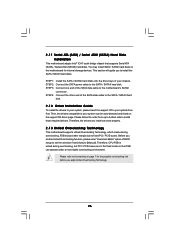
...install those required drivers. STEP 2: Connect the SATA power cable to your system can work properly. 2 . 1 3 Untied Overclocking Technology This motherboard supports Untied Overclocking Technology, which means during overclocking, but PCI / PCIE buses are in the fixed mode so that supports Serial ATA (SATA)... disks. STEP 4: Connect the other end of the SATA data cable to your optical drive first. Then, the drivers compatible to the motherboard's SATAII connector. Please follow the order from [Auto] to fixed PCI / PCIE buses. Therefore, CPU FSB is untied during overclocking,...
...install those required drivers. STEP 2: Connect the SATA power cable to your system can work properly. 2 . 1 3 Untied Overclocking Technology This motherboard supports Untied Overclocking Technology, which means during overclocking, but PCI / PCIE buses are in the fixed mode so that supports Serial ATA (SATA)... disks. STEP 4: Connect the other end of the SATA data cable to your optical drive first. Then, the drivers compatible to the motherboard's SATAII connector. Please follow the order from [Auto] to fixed PCI / PCIE buses. Therefore, CPU FSB is untied during overclocking,...

User Manual
Page 27
... with the following BIOS setup screens and descriptions are for reference purpose only, and they may also restart by pressing the reset button on the motherboard stores the BIOS SETUP UTILITY. The BIOS FWH chip on the system chassis. Please press during the Power-On-Self-Test (POST) to get into...
... with the following BIOS setup screens and descriptions are for reference purpose only, and they may also restart by pressing the reset button on the motherboard stores the BIOS SETUP UTILITY. The BIOS FWH chip on the system chassis. Please press during the Power-On-Self-Test (POST) to get into...

User Manual
Page 30
...the CPU from overheated. Hyper Threading Technology To enable this feature, it shows "Unlocked", you changing the ratio value of this motherboard. This option will be enabled in order to execute code. is supported through the native processor instructions HLT and MWAIT and ... No-Excute Memory Protection No-Execution (NX) Memory Protection Technology is a read -only item, which displays the ratio actual value of this motherboard. This option will be hidden if the installed CPU does not support Intel (R) Virtualization Technology. Set to enable power 30 Intel (R) SpeedStep(...
...the CPU from overheated. Hyper Threading Technology To enable this feature, it shows "Unlocked", you changing the ratio value of this motherboard. This option will be enabled in order to execute code. is supported through the native processor instructions HLT and MWAIT and ... No-Excute Memory Protection No-Execution (NX) Memory Protection Technology is a read -only item, which displays the ratio actual value of this motherboard. This option will be hidden if the installed CPU does not support Intel (R) Virtualization Technology. Set to enable power 30 Intel (R) SpeedStep(...

