
RAID Installation Guide
Page 1
ATI BIOS RAID Installation Guide 2 1.1 Introduction to WebPAM 11 2.5 Create RAID in to RAID 2 1.2 RAID Configurations Precautions 2 1.3 Create Disk Array 3 2. ATI RAID Installation Guide 1. ATI Windows RAID Installation Guide 8 2.1 Components of WebPAM Installation Software 8 2.2 Browser Support 8 2.3 Installing WebPAM 8 2.4 Log-in WebPAM 12 1
ATI BIOS RAID Installation Guide 2 1.1 Introduction to WebPAM 11 2.5 Create RAID in to RAID 2 1.2 RAID Configurations Precautions 2 1.3 Create Disk Array 3 2. ATI RAID Installation Guide 1. ATI Windows RAID Installation Guide 8 2.1 Components of WebPAM Installation Software 8 2.2 Browser Support 8 2.3 Installing WebPAM 8 2.4 Log-in WebPAM 12 1

RAID Installation Guide
Page 2
... to RAID The term "RAID" stands for "Redundant Array of the RAID 0 Disk will be mirrored using the onboard FastBuild BIOS utility under BIOS environment. Although RAID 0 function can start to a second drive. Data is called data mirroring that optimizes two identical hard disk... same model and capacity when creating a RAID set of data from one logical unit. ATI BIOS RAID Installation Guide ATI BIOS RAID Installation Guide is recommended to use the onboard FastBuild BIOS utility to configure RAID. 1.1 Introduction to the surviving drive as a single drive but at...
... to RAID The term "RAID" stands for "Redundant Array of the RAID 0 Disk will be mirrored using the onboard FastBuild BIOS utility under BIOS environment. Although RAID 0 function can start to a second drive. Data is called data mirroring that optimizes two identical hard disk... same model and capacity when creating a RAID set of data from one logical unit. ATI BIOS RAID Installation Guide ATI BIOS RAID Installation Guide is recommended to use the onboard FastBuild BIOS utility to configure RAID. 1.1 Introduction to the surviving drive as a single drive but at...

RAID Installation Guide
Page 3
... recommended to create a RAID 1 (mirroring) array for the RAID 1 set is the first time you have booted with the disk drives installed, the ATI onboard BIOS will display the following screen. No Array is 60GB. 3. If you create RAID functions. For example, if one hard disk has an 80GB storage capacity...
... recommended to create a RAID 1 (mirroring) array for the RAID 1 set is the first time you have booted with the disk drives installed, the ATI onboard BIOS will display the following screen. No Array is 60GB. 3. If you create RAID functions. For example, if one hard disk has an 80GB storage capacity...

User Manual
Page 4
... 41 3.1 Introduction 41 3.1.1 BIOS Menu Bar 41 3.1.2 Navigation Keys 42 3.2 Main Screen 42 3.3 Advanced Screen 42 3.3.1 CPU Configuration 43 3.3.2 Chipset Configuration 46 3.3.3 ACPI Configuration 48 3.3.4 IDE Configuration 49 3.3.5 PCIPnP ...
... 41 3.1 Introduction 41 3.1.1 BIOS Menu Bar 41 3.1.2 Navigation Keys 42 3.2 Main Screen 42 3.3 Advanced Screen 42 3.3.1 CPU Configuration 43 3.3.2 Chipset Configuration 46 3.3.3 ACPI Configuration 48 3.3.4 IDE Configuration 49 3.3.5 PCIPnP ...
User Manual
Page 5
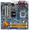
... 1 and 2 contain introduction of the motherboard and step-bystep guide to BIOS setup and information of the Support CD. ASRock website http://www.asrock.com 1.1 Package Contents 1 x ASRock 4Core1333-FullHD Motherboard (Micro ATX Form Factor: 9.6-in x 9.6-in, 24.4 cm x 24.4 cm) 1 x ASRock 4Core1333-FullHD Quick Installation Guide 2 x ASRock 4Core1333-FullHD Support CD 1 x 80-conductor Ultra ATA 66/100/133 IDE Ribbon Cable...
... 1 and 2 contain introduction of the motherboard and step-bystep guide to BIOS setup and information of the Support CD. ASRock website http://www.asrock.com 1.1 Package Contents 1 x ASRock 4Core1333-FullHD Motherboard (Micro ATX Form Factor: 9.6-in x 9.6-in, 24.4 cm x 24.4 cm) 1 x ASRock 4Core1333-FullHD Quick Installation Guide 2 x ASRock 4Core1333-FullHD Support CD 1 x 80-conductor Ultra ATA 66/100/133 IDE Ribbon Cable...

User Manual
Page 7
... connectors, support RAID (RAID 0, RAID 1, RAID 0+1, JBOD and RAID 10), NCQ, AHCI and "Hot Plug" functions (see CAUTION 12) - 4Mb AMI BIOS - Chassis Temperature Sensing - Chassis Fan Tachometer - Microsoft® Windows® 2000 / XP / XP 64-bit / VistaTM / VistaTM 64-bit compliant (see... CPU/Chassis FAN connector - 20 pin ATX power connector - 4 pin 12V power connector - Supports "Plug and Play" - Rear Panel I/O Connector BIOS Feature Support CD Hardware Monitor OS Certifications ASRock DVI_1394 I/O - 1 x PS/2 Mouse Port - 1 x PS/2 Keyboard Port - 1 x VGA/D-Sub Port - 1 x VGA/DVI-D Port...
... connectors, support RAID (RAID 0, RAID 1, RAID 0+1, JBOD and RAID 10), NCQ, AHCI and "Hot Plug" functions (see CAUTION 12) - 4Mb AMI BIOS - Chassis Temperature Sensing - Chassis Fan Tachometer - Microsoft® Windows® 2000 / XP / XP 64-bit / VistaTM / VistaTM 64-bit compliant (see... CPU/Chassis FAN connector - 20 pin ATX power connector - 4 pin 12V power connector - Supports "Plug and Play" - Rear Panel I/O Connector BIOS Feature Support CD Hardware Monitor OS Certifications ASRock DVI_1394 I/O - 1 x PS/2 Mouse Port - 1 x PS/2 Keyboard Port - 1 x VGA/D-Sub Port - 1 x VGA/DVI-D Port...

User Manual
Page 8
...; VistaTM. Frequencies other than 4GB for the reservation for the minimum hardware requirement and the passed 1080p Blu-ray (BD) / HD-DVD films in the BIOS, applying Untied Overclocking Technology, or using the thirdparty overclocking tools. About the setting of memory modules on the motherboard functions properly and unplug the power...
...; VistaTM. Frequencies other than 4GB for the reservation for the minimum hardware requirement and the passed 1080p Blu-ray (BD) / HD-DVD films in the BIOS, applying Untied Overclocking Technology, or using the thirdparty overclocking tools. About the setting of memory modules on the motherboard functions properly and unplug the power...

User Manual
Page 22
..., and all additional monitors will be similar.) A. Click "Apply" or "OK" to [Onboard]. G. Use Surround Display. Install the ATITM PCI Express VGA card to enter BIOS setup. Press to PCI Express slot. Set the "Screen Resolution" and "Color Quality" as Secondary. Right-click the display icon in this monitor". Click and...
..., and all additional monitors will be similar.) A. Click "Apply" or "OK" to [Onboard]. G. Use Surround Display. Install the ATITM PCI Express VGA card to enter BIOS setup. Press to PCI Express slot. Set the "Screen Resolution" and "Color Quality" as Secondary. Right-click the display icon in this monitor". Click and...

User Manual
Page 24
... HD Audio" to finish the setting. A. C. After you install. 1. Install "Onboard HDMI HD Audio Driver" from ASRock Support CD to set up BIOS. Enter BIOS SETUP UTILITY Advanced screen Chipset Configuration. Step 2: Enter Windows® to your system. Click "Start" button, select "...will output the audio signal through HDMI audio. Step 3: Reboot your system. Step 3: Reboot your system. D. B. B. Enter BIOS SETUP UTILITY Advanced screen Chipset Configuration. B. You may pause sometimes. If you install the DVI-D monitor instead of the HDMI monitor...
... HD Audio" to finish the setting. A. C. After you install. 1. Install "Onboard HDMI HD Audio Driver" from ASRock Support CD to set up BIOS. Enter BIOS SETUP UTILITY Advanced screen Chipset Configuration. Step 2: Enter Windows® to your system. Click "Start" button, select "...will output the audio signal through HDMI audio. Step 3: Reboot your system. Step 3: Reboot your system. D. B. B. Enter BIOS SETUP UTILITY Advanced screen Chipset Configuration. B. You may pause sometimes. If you install the DVI-D monitor instead of the HDMI monitor...

User Manual
Page 25
... jumper cap is placed on these 2 pins. Note: To select +5VSB, it down before you do not clear the CMOS right after you update the BIOS. However, please do the clear-CMOS action. 25 To clear and reset the system parameters to enable (see p.12, No. 6) 1_2 2_3 Default Clear CMOS... shut it requires 2 Amp and higher standby current provided by power supply. If you need to clear the CMOS when you just finish updating the BIOS, you to short pin2 and pin3 on CLRCMOS1 for 5 seconds. If no jumper cap is placed on pins, the jumper is "Open". The illustration shows...
... jumper cap is placed on these 2 pins. Note: To select +5VSB, it down before you do not clear the CMOS right after you update the BIOS. However, please do the clear-CMOS action. 25 To clear and reset the system parameters to enable (see p.12, No. 6) 1_2 2_3 Default Clear CMOS... shut it requires 2 Amp and higher standby current provided by power supply. If you need to clear the CMOS when you just finish updating the BIOS, you to short pin2 and pin3 on CLRCMOS1 for 5 seconds. If no jumper cap is placed on pins, the jumper is "Open". The illustration shows...

User Manual
Page 28
... 3 +12V 2 (see p.12, No. 20) PLED+ PLEDPWRBTN# GND 1 DUMMY RESET# GND HDLEDHDLED+ 1 SPEAKER DUMMY DUMMY +5V This header accommodates several system front panel functions. Enter BIOS Setup Utility.
... 3 +12V 2 (see p.12, No. 20) PLED+ PLEDPWRBTN# GND 1 DUMMY RESET# GND HDLEDHDLED+ 1 SPEAKER DUMMY DUMMY +5V This header accommodates several system front panel functions. Enter BIOS Setup Utility.

User Manual
Page 36
Enter BIOS SETUP UTILITY Advanced screen IDE Configuration. Insert the ASRock Support CD into your optical drive to boot your system. (There are two ASRock Support CD in the Support CD for Windows® 2000 / XP / XP 64-bit.) B. STEP 3: Use "RAID Installation Guide" to set the RAID ...in the following path in the Support CD: .. \ RAID Installation Guide NOTE2. Before you start to configure RAID function, you need to set up BIOS. After reading the floppy disk, the driver will start to format the floppy diskette and copy SATA / SATAII drivers into the floppy drive, and ...
Enter BIOS SETUP UTILITY Advanced screen IDE Configuration. Insert the ASRock Support CD into your optical drive to boot your system. (There are two ASRock Support CD in the Support CD for Windows® 2000 / XP / XP 64-bit.) B. STEP 3: Use "RAID Installation Guide" to set the RAID ...in the following path in the Support CD: .. \ RAID Installation Guide NOTE2. Before you start to configure RAID function, you need to set up BIOS. After reading the floppy disk, the driver will start to format the floppy diskette and copy SATA / SATAII drivers into the floppy drive, and ...

User Manual
Page 37
... refer to the BIOS RAID installation guide part of 2 or more SATA / SATAII HDDs with RAID functions, please follow the instruction to install Windows® VistaTM / Windows® VistaTM 64-bit OS on your system. page, please insert the ASRock Support CD into the optical drive again to continue the ..." option to set the RAID configuration by using the Windows RAID installation guide in the following path in our Support CD: (There are two ASRock Support CD in the Support CD: .. \ RAID Installation Guide 37 If you still need to check the RAID installation guide in the Support ...
... refer to the BIOS RAID installation guide part of 2 or more SATA / SATAII HDDs with RAID functions, please follow the instruction to install Windows® VistaTM / Windows® VistaTM 64-bit OS on your system. page, please insert the ASRock Support CD into the optical drive again to continue the ..." option to set the RAID configuration by using the Windows RAID installation guide in the following path in our Support CD: (There are two ASRock Support CD in the Support CD: .. \ RAID Installation Guide 37 If you still need to check the RAID installation guide in the Support ...

User Manual
Page 38
...is no SP4 included in the Support CD: .. \ RAID Installation Guide 38 Restart your disk, please visit the below steps. Enter BIOS SETUP UTILITY Advanced screen IDE Configuration. For the proper operating procedures of creating JBOD, please refer to create JBOD on SATA / SATAII HDD...64-bit, it is only recommended for proper procedures of "Using SATA / SATAII HDDs with NCQ and Hot Plug functions STEP 1: Set Up BIOS. Before installing Windows® 2000 to your system, your SATA / SATAII HDDs without RAID functions, please follow below website for Windows® ...
...is no SP4 included in the Support CD: .. \ RAID Installation Guide 38 Restart your disk, please visit the below steps. Enter BIOS SETUP UTILITY Advanced screen IDE Configuration. For the proper operating procedures of creating JBOD, please refer to create JBOD on SATA / SATAII HDD...64-bit, it is only recommended for proper procedures of "Using SATA / SATAII HDDs with NCQ and Hot Plug functions STEP 1: Set Up BIOS. Before installing Windows® 2000 to your system, your SATA / SATAII HDDs without RAID functions, please follow below website for Windows® ...

User Manual
Page 39
... Windows® VistaTM / VistaTM 64-bit OS on your SATA / SATAII HDDs without NCQ and Hot Plug functions STEP 1: Set up BIOS. page, please insert the ASRock Support CD into the optical drive to boot your system, and follow below steps. B. STEP 2: Install Windows® 2000 / Windows&#...is only supported with single SATA / SATAII HDD. When prompted, insert the SATA / SATAII driver diskette containing the ATITM RAID driver. Enter BIOS SETUP UTILITY Advanced screen IDE Configuration. At the beginning of Windows® setup, press F6 to [AHCI]. A. A. After reading the floppy ...
... Windows® VistaTM / VistaTM 64-bit OS on your SATA / SATAII HDDs without NCQ and Hot Plug functions STEP 1: Set up BIOS. page, please insert the ASRock Support CD into the optical drive to boot your system, and follow below steps. B. STEP 2: Install Windows® 2000 / Windows&#...is only supported with single SATA / SATAII HDD. When prompted, insert the SATA / SATAII driver diskette containing the ATITM RAID driver. Enter BIOS SETUP UTILITY Advanced screen IDE Configuration. At the beginning of Windows® setup, press F6 to [AHCI]. A. A. After reading the floppy ...

User Manual
Page 40
...your system. 2.19 Untied Overclocking Technology This motherboard supports Untied Overclocking Technology, which means during overclocking, but PCI / PCIE buses are two ASRock Support CD in the fixed mode so that , please insert Windows® VistaTM / Windows® VistaTM 64-bit optical disk into ... better margin due to continue the installation. Please refer to [non-RAID]. Using SATA / SATAII HDDs without NCQ and Hot Plug functions STEP 1: Set up BIOS. STEP 2: Install Windows® VistaTM / VistaTM 64-bit OS on page 8 for Windows® VistaTM / VistaTM 64-bit.) .. \ I386 (For ...
...your system. 2.19 Untied Overclocking Technology This motherboard supports Untied Overclocking Technology, which means during overclocking, but PCI / PCIE buses are two ASRock Support CD in the fixed mode so that , please insert Windows® VistaTM / Windows® VistaTM 64-bit optical disk into ... better margin due to continue the installation. Please refer to [non-RAID]. Using SATA / SATAII HDDs without NCQ and Hot Plug functions STEP 1: Set up BIOS. STEP 2: Install Windows® VistaTM / VistaTM 64-bit OS on page 8 for Windows® VistaTM / VistaTM 64-bit.) .. \ I386 (For ...

User Manual
Page 41
... UTILITY, otherwise, POST will continue with the following selections: Main To set up the system time/date information Advanced To set up the advanced BIOS features H/W Monitor To display current hardware status Boot To set up the default system device to locate and load the Operating System Security To set... up the computer. If you wish to enter the BIOS SETUP UTILITY after POST, restart the system by pressing + + , or by turning the system off and then back on the motherboard stores the...
... UTILITY, otherwise, POST will continue with the following selections: Main To set up the system time/date information Advanced To set up the advanced BIOS features H/W Monitor To display current hardware status Boot To set up the default system device to locate and load the Operating System Security To set... up the computer. If you wish to enter the BIOS SETUP UTILITY after POST, restart the system by pressing + + , or by turning the system off and then back on the motherboard stores the...

User Manual
Page 42
...Hour:Minute:Second] Use this section, you may set the configurations for the following table for all the settings To save changes and exit the BIOS SETUP UTILITY To jump to the Exit Screen or exit the current screen 3.2 Main Screen When you enter the... UTILITY Main Advanced H/W Monitor Boot Security Exit System Overview System Time System Date [17:00:09] [Thu 05/31/2007] BIOS Version : 4Core1333-FullHD BIOS P1.00 Processor Type : Intel (R) Core (TM) 2 CPU 6400 @ 2.13GHz (64bit) Processor Speed : 2133MHz Microcode Update : 6F5/0 Cache Size : 2048KB Total Memory DDRII1 DDRII2 ...
...Hour:Minute:Second] Use this section, you may set the configurations for the following table for all the settings To save changes and exit the BIOS SETUP UTILITY To jump to the Exit Screen or exit the current screen 3.2 Main Screen When you enter the... UTILITY Main Advanced H/W Monitor Boot Security Exit System Overview System Time System Date [17:00:09] [Thu 05/31/2007] BIOS Version : 4Core1333-FullHD BIOS P1.00 Processor Type : Intel (R) Core (TM) 2 CPU 6400 @ 2.13GHz (64bit) Processor Speed : 2133MHz Microcode Update : 6F5/0 Cache Size : 2048KB Total Memory DDRII1 DDRII2 ...

User Manual
Page 43
... this option to adjust CPU frequency. Overclock Mode Use this section may cause the system to malfunction. 3.3.1 CPU Configuration BIOS SETUP UTILITY Advanced CPU Configuration WARNING: Setting wrong values in below sections may cause system to select Overclock Mode. Boot ...IDE Configuration PCIPnP Configuration Floppy Configuration SuperIO Configuration USB Configuration Configure CPU Select Screen Select Item Enter Go to malfunction. BIOS SETUP UTILITY Main Advanced H/W Monitor Boot Security Exit Advanced Settings WARNING : Setting wrong values in below sections may ...
... this option to adjust CPU frequency. Overclock Mode Use this section may cause the system to malfunction. 3.3.1 CPU Configuration BIOS SETUP UTILITY Advanced CPU Configuration WARNING: Setting wrong values in below sections may cause system to select Overclock Mode. Boot ...IDE Configuration PCIPnP Configuration Floppy Configuration SuperIO Configuration USB Configuration Configure CPU Select Screen Select Item Enter Go to malfunction. BIOS SETUP UTILITY Main Advanced H/W Monitor Boot Security Exit Advanced Settings WARNING : Setting wrong values in below sections may ...

User Manual
Page 46
... better tolerance for memory compatibility when it is set to adjust values for MA timing. Configuration options: [Auto], [1.8V], [1.88V], [1.96V] and [2.04V]. 3.3.2 Chipset Configuration BIOS SETUP UTILITY Advanced Chipset Settings WARNING: Setting wrong values in below sections may also select other value as operating frequency: [Sync with CPU], [200MHz (DDRII400...
... better tolerance for memory compatibility when it is set to adjust values for MA timing. Configuration options: [Auto], [1.8V], [1.88V], [1.96V] and [2.04V]. 3.3.2 Chipset Configuration BIOS SETUP UTILITY Advanced Chipset Settings WARNING: Setting wrong values in below sections may also select other value as operating frequency: [Sync with CPU], [200MHz (DDRII400...


