
Getting Started Guide
Page 2
...furnished under a license agreement included with limited rights only as translation, transformation, or adaptation) without written permission from 3Com Corporation. 3Com Corporation reserves the right to revise this documentation and to make improvements or changes in the product(s) and/or the... you subject to recognized environmental standards. Microsoft, MS-DOS, Windows, and Windows NT are registered trademarks of Life Statement 3Com processes allow for the Software. Novell and NetWare are registered trademarks of Intel Corporation. ENVIRONMENTAL STATEMENT It is a registered ...
...furnished under a license agreement included with limited rights only as translation, transformation, or adaptation) without written permission from 3Com Corporation. 3Com Corporation reserves the right to revise this documentation and to make improvements or changes in the product(s) and/or the... you subject to recognized environmental standards. Microsoft, MS-DOS, Windows, and Windows NT are registered trademarks of Life Statement 3Com processes allow for the Software. Novell and NetWare are registered trademarks of Intel Corporation. ENVIRONMENTAL STATEMENT It is a registered ...
Getting Started Guide
Page 3
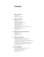
... Conventions 5 Related Documentation 5 1 PRODUCT OVERVIEW Introduction 7 Switch 4800G 24-Port 8 Switch 4800G PWR 48-Port 11 Switch 4800G PWR 24-Port 13 Switch 4800G 24-Port SFP 17 Switch 4800G 48-Port 18 System Specifications of the Switch 4800G Series 22 Pluggable Modules 22 Optional Interface Modules 23 CX4 Cable 24 2 PREPARATING TO INSTALL THE SWITCH Safety Precautions 25 Installation Site 25 Installation...
... Conventions 5 Related Documentation 5 1 PRODUCT OVERVIEW Introduction 7 Switch 4800G 24-Port 8 Switch 4800G PWR 48-Port 11 Switch 4800G PWR 24-Port 13 Switch 4800G 24-Port SFP 17 Switch 4800G 48-Port 18 System Specifications of the Switch 4800G Series 22 Pluggable Modules 22 Optional Interface Modules 23 CX4 Cable 24 2 PREPARATING TO INSTALL THE SWITCH Safety Precautions 25 Installation Site 25 Installation...
Getting Started Guide
Page 4
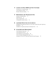
... Configuration System Failure 74 A LIGHTNING PROTECTION FOR THE SWITCH Installating the Lightning Arrester for AC Power (Socket Strip with Lightning Protection) 75 Installation of Lightning Arrester for Network Port 76 B 3COM NETWORK MANAGEMENT 3Com Network Supervisor 79 3Com Network Director 79 3Com Network Access Manager 80 3Com Enterprise Management Suite 81 Integration Kit with HP OpenView...
... Configuration System Failure 74 A LIGHTNING PROTECTION FOR THE SWITCH Installating the Lightning Arrester for AC Power (Socket Strip with Lightning Protection) 75 Installation of Lightning Arrester for Network Port 76 B 3COM NETWORK MANAGEMENT 3Com Network Supervisor 79 3Com Network Director 79 3Com Network Access Manager 80 3Com Enterprise Management Suite 81 Integration Kit with HP OpenView...
Getting Started Guide
Page 5
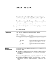
..., and maintain software and hardware. ABOUT THIS GUIDE Conventions This guide describes the 3Com® Switch 4800G and how to manage your Switch 4800G. Table 1 Notice Icons Icon Notice Type n Information note Description Information that are responsible for managing your Switch 4800G. ■ Switch 4800G Configuration Guide- Related Documentation The following manuals offer additional information necessary for configuring, using...
..., and maintain software and hardware. ABOUT THIS GUIDE Conventions This guide describes the 3Com® Switch 4800G and how to manage your Switch 4800G. Table 1 Notice Icons Icon Notice Type n Information note Description Information that are responsible for managing your Switch 4800G. ■ Switch 4800G Configuration Guide- Related Documentation The following manuals offer additional information necessary for configuring, using...

Getting Started Guide
Page 6
These documents are available in the Release Notes. If information in this guide differs from information in the release notes, use the information in Adobe Acrobat Reader Portable Document Format (PDF) on the 3Com World Wide Web site: http://www.3com.com/ 6 ABOUT THIS GUIDE ■ Switch 4800G Release Notes - Contains the latest information about your router or on the CD-ROM that accompanies your product.
These documents are available in the Release Notes. If information in this guide differs from information in the release notes, use the information in Adobe Acrobat Reader Portable Document Format (PDF) on the 3Com World Wide Web site: http://www.3com.com/ 6 ABOUT THIS GUIDE ■ Switch 4800G Release Notes - Contains the latest information about your router or on the CD-ROM that accompanies your product.
Getting Started Guide
Page 7
... stack and can also be used for connecting server groups in data centers. The Switch 4800G are Gigabit Ethernet switching products developed by Hangzhou 3Com Technologies Co., Ltd. (hereinafter referred to as the Switch 4800G) are designed to operate at a time. The Switch 4800G support diversified service features, IPv6 forwarding, and routing function, and provide 10GE extended module...
... stack and can also be used for connecting server groups in data centers. The Switch 4800G are Gigabit Ethernet switching products developed by Hangzhou 3Com Technologies Co., Ltd. (hereinafter referred to as the Switch 4800G) are designed to operate at a time. The Switch 4800G support diversified service features, IPv6 forwarding, and routing function, and provide 10GE extended module...
Getting Started Guide
Page 8
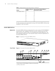
8 CHAPTER 1: PRODUCT OVERVIEW Table 3 Mapping between two ports forming a Combo port Model Switch 4800G 48-Port 1000Base-X SFP port Auto-sensing 10/100/1000Base-T number Ethernet port number 25 17 26 18 27 19 28 20 29 21 30.../100/1000Base-T Ethernet port status LEDs (2) SFP port status LEDs Figure 1 Appearance of the Switch 4800G 24-Port Front Panel Figure 2 Front panel of the Switch 4800G, LEDs are also equipped on the rear panel. Switch 4800G 24-Port Appearance The Switch 4800G 24-Port provides twenty-four auto-sensing 10/100/1000BASE-T Ethernet ports, four 1000Base-X SFP...
8 CHAPTER 1: PRODUCT OVERVIEW Table 3 Mapping between two ports forming a Combo port Model Switch 4800G 48-Port 1000Base-X SFP port Auto-sensing 10/100/1000Base-T number Ethernet port number 25 17 26 18 27 19 28 20 29 21 30.../100/1000Base-T Ethernet port status LEDs (2) SFP port status LEDs Figure 1 Appearance of the Switch 4800G 24-Port Front Panel Figure 2 Front panel of the Switch 4800G, LEDs are also equipped on the rear panel. Switch 4800G 24-Port Appearance The Switch 4800G 24-Port provides twenty-four auto-sensing 10/100/1000BASE-T Ethernet ports, four 1000Base-X SFP...
Getting Started Guide
Page 9
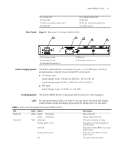
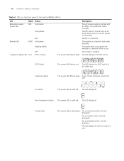
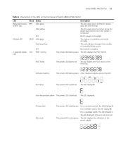
...LED for extended module slot 1 (9) Mode LED (4) 7-segment digital LED (6) RPS LED (8) LED for heat dissipation. Table 4 LEDs on the front panel of the Switch 4800G 24-Port LED Mode LED Power LED Mark Status Mode Speed Solid green Duplex Solid yellow PWR Solid green Flashing green (1 Hz) Solid red Flashing... a power failure occurs. Only the recommended RPS can adopt AC input, or 12 V RPS input, or both to 13.2 VDC Cooling System The Switch 4800G 24-Port is disconnected. The power is equipped with four fans for extended module slot 2 (10) Mode button Rear Panel Figure 3 Rear panel of...
...LED for extended module slot 1 (9) Mode LED (4) 7-segment digital LED (6) RPS LED (8) LED for heat dissipation. Table 4 LEDs on the front panel of the Switch 4800G 24-Port LED Mode LED Power LED Mark Status Mode Speed Solid green Duplex Solid yellow PWR Solid green Flashing green (1 Hz) Solid red Flashing... a power failure occurs. Only the recommended RPS can adopt AC input, or 12 V RPS input, or both to 13.2 VDC Cooling System The Switch 4800G 24-Port is disconnected. The power is equipped with four fans for extended module slot 2 (10) Mode button Rear Panel Figure 3 Rear panel of...
Getting Started Guide
Page 10
...displays F. The LED displays 1 if there is in position and works normally. The switch does not support the module or a module failure occurs. For a member switch, the LED displays S. The LED displays t. For a candidate switch, the LED displays c. Fan failure The power LED is solid green. Cluster state... The power LED is solid red. POST failed The power LED flashes red The LED flashes the POST test ID of the Switch 4800G 24-Port LED Redundant power system LED Mark Status RPS Solid green Solid yellow Module LED OFF MOD Solid green Flashing yellow OFF...
...displays F. The LED displays 1 if there is in position and works normally. The switch does not support the module or a module failure occurs. For a member switch, the LED displays S. The LED displays t. For a candidate switch, the LED displays c. Fan failure The power LED is solid green. Cluster state... The power LED is solid red. POST failed The power LED flashes red The LED flashes the POST test ID of the Switch 4800G 24-Port LED Redundant power system LED Mark Status RPS Solid green Solid yellow Module LED OFF MOD Solid green Flashing yellow OFF...
Getting Started Guide
Page 11
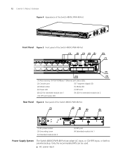
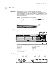
... being received or sent The port fails the POST. The port failed the POST. No link is present. Figure 5 shows the appearance of the Switch 4800G 24-Port LED 10/100/1000Base-T port status LED Mark Status - The port works in the full duplex mode. No link is present.... Switch 4800G PWR 48-Port Appearance The Switch 4800G PWR 48-Port provides forty-eight auto-sensing 10/100/1000BASE-T Ethernet ports, four 1000Base-X SFP ports, and one console port on the...
... being received or sent The port fails the POST. The port failed the POST. No link is present. Figure 5 shows the appearance of the Switch 4800G 24-Port LED 10/100/1000Base-T port status LED Mark Status - The port works in the full duplex mode. No link is present.... Switch 4800G PWR 48-Port Appearance The Switch 4800G PWR 48-Port provides forty-eight auto-sensing 10/100/1000BASE-T Ethernet ports, four 1000Base-X SFP ports, and one console port on the...
Getting Started Guide
Page 12
... adopt AC input, or 12V RPS input, or both to provide backup. 12 CHAPTER 1: PRODUCT OVERVIEW Figure 4 Appearance of the Switch 4800G PWR 48-Port Front Panel Figure 5 Front panel of the Switch 4800G PWR 48-Port (1) (2) (3) (4) (5) (6) (7) (8 ) (10) (9) (1) Auto-sensing 10/100/1000Base-T Ethernet port status ... 1 (9) LED for extended module slot 2 (10) SFP port status LED Rear Panel Figure 6 Rear panel of the Switch 4800G PWR 48-Port (1) (2) (3) (4) (5) (1) AC power socket (3) Grounding screw (5) Extended module slot 2 (2) RPS port (4) Extended module slot 1 Power Supply ...
... adopt AC input, or 12V RPS input, or both to provide backup. 12 CHAPTER 1: PRODUCT OVERVIEW Figure 4 Appearance of the Switch 4800G PWR 48-Port Front Panel Figure 5 Front panel of the Switch 4800G PWR 48-Port (1) (2) (3) (4) (5) (6) (7) (8 ) (10) (9) (1) Auto-sensing 10/100/1000Base-T Ethernet port status ... 1 (9) LED for extended module slot 2 (10) SFP port status LED Rear Panel Figure 6 Rear panel of the Switch 4800G PWR 48-Port (1) (2) (3) (4) (5) (1) AC power socket (3) Grounding screw (5) Extended module slot 2 (2) RPS port (4) Extended module slot 1 Power Supply ...
Getting Started Guide
Page 13
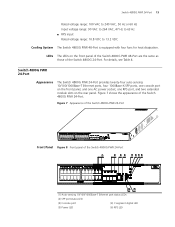
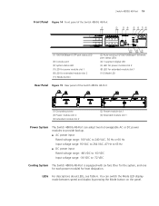
...Switch 4800G PWR 48-Port are the same as those of the Switch 4800G 24-Port. Figure 7 Appearance of the Switch 4800G PWR 24-Port Front Panel Figure 8 Front panel of the Switch 4800G PWR 24-Port. Switch 4800G... Rated voltage range: 10.8 VDC to 13.2 VDC Cooling System The Switch 4800G PWR 48-Port is equipped with four fans for heat dissipation. For details, see Table 4.... Figure 7 shows the appearance of the Switch 4800G PWR 24-Port (1) (2) (3) (4) (5) (6) (7) (8) (10) (9) (1) Auto-sensing 10/100/1000Base-T Ethernet...
...Switch 4800G PWR 48-Port are the same as those of the Switch 4800G 24-Port. Figure 7 Appearance of the Switch 4800G PWR 24-Port Front Panel Figure 8 Front panel of the Switch 4800G PWR 24-Port. Switch 4800G... Rated voltage range: 10.8 VDC to 13.2 VDC Cooling System The Switch 4800G PWR 48-Port is equipped with four fans for heat dissipation. For details, see Table 4.... Figure 7 shows the appearance of the Switch 4800G PWR 24-Port (1) (2) (3) (4) (5) (6) (7) (8) (10) (9) (1) Auto-sensing 10/100/1000Base-T Ethernet...
Getting Started Guide
Page 14
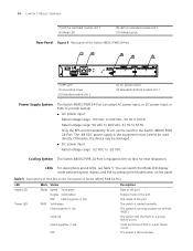
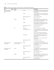
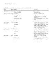
...-on the panel. You can be damaged. ■ DC power input Rated voltage range: -52 VDC to 63 Hz Only the RPS recommended by 3Com can switch the Mode LED display mode between speed, duplex, and PoE by pressing the Mode button on self-test (POST). Table 5 Descriptions of the LEDs on... the front panel of Switch 4800G PWR 24-Port LED Mode LED Power LED Mark Status Mode Speed Solid green Duplex Solid yellow PoE Flashing green (1 Hz) PWR Solid green Flashing...
...-on the panel. You can be damaged. ■ DC power input Rated voltage range: -52 VDC to 63 Hz Only the RPS recommended by 3Com can switch the Mode LED display mode between speed, duplex, and PoE by pressing the Mode button on self-test (POST). Table 5 Descriptions of the LEDs on... the front panel of Switch 4800G PWR 24-Port LED Mode LED Power LED Mark Status Mode Speed Solid green Duplex Solid yellow PoE Flashing green (1 Hz) PWR Solid green Flashing...
Getting Started Guide
Page 15
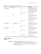
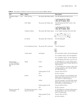
Switch 4800G PWR 24-Port 15 Table 5 Descriptions of the LEDs on the front panel of the failed test. The module is solid red. A bar rotates clockwise around the LED. The LED displays F. For a member switch, the LED displays S. For a candidate switch, the LED displays c. Over-temperature alarm The power LED...Fan failure The power LED is only one unit. POST failed The power LED flashes red The LED flashes the POST test ID of Switch 4800G PWR 24-Port LED Redundant power system LED Mark Status RPS Solid green Solid yellow Module LED OFF MOD Solid green Flashing yellow OFF...
Switch 4800G PWR 24-Port 15 Table 5 Descriptions of the LEDs on the front panel of the failed test. The module is solid red. A bar rotates clockwise around the LED. The LED displays F. For a member switch, the LED displays S. For a candidate switch, the LED displays c. Over-temperature alarm The power LED...Fan failure The power LED is only one unit. POST failed The power LED flashes red The LED flashes the POST test ID of Switch 4800G PWR 24-Port LED Redundant power system LED Mark Status RPS Solid green Solid yellow Module LED OFF MOD Solid green Flashing yellow OFF...
Getting Started Guide
Page 16
... link is not a powered device (PD), so the port cannot supply power. The port fails the POST. No link is present. The required power of Switch 4800G PWR 24-Port LED Mark Status 10/100/1000Base-T Ethernet port status LED Speed Duplex PoE Green Yellow Flashing yellow (3 Hz) OFF Green Yellow Flashing...
... link is not a powered device (PD), so the port cannot supply power. The port fails the POST. No link is present. The required power of Switch 4800G PWR 24-Port LED Mark Status 10/100/1000Base-T Ethernet port status LED Speed Duplex PoE Green Yellow Flashing yellow (3 Hz) OFF Green Yellow Flashing...
Getting Started Guide
Page 17
...-Port SFP Front Panel Figure 11 Front panel of the Switch 4800G 24-Port SFP (1) (2) (3) (4) (5) (6) (7) (8) (10) (9) (1) Auto-sensing 10/100/1000Base-T Ethernet port status LEDs (2) Console port (3) 7-segment digital LED (4) Mode button (5) Mode LED (6) Power LED...(9) LED for extended module slot 2 (10) SFP port status LED Rear Panel Figure 12 Rear panel of the Switch 4800G 24-Port SFP. Switch 4800G 24-Port SFP 17 Switch 4800G 24-Port SFP Appearance The Switch 4800G 24-Port SFP provides forty-eight auto-sensing 10/100/1000Base-T Ethernet ports, four 1000Base-X SFP ports and one...
...-Port SFP Front Panel Figure 11 Front panel of the Switch 4800G 24-Port SFP (1) (2) (3) (4) (5) (6) (7) (8) (10) (9) (1) Auto-sensing 10/100/1000Base-T Ethernet port status LEDs (2) Console port (3) 7-segment digital LED (4) Mode button (5) Mode LED (6) Power LED...(9) LED for extended module slot 2 (10) SFP port status LED Rear Panel Figure 12 Rear panel of the Switch 4800G 24-Port SFP. Switch 4800G 24-Port SFP 17 Switch 4800G 24-Port SFP Appearance The Switch 4800G 24-Port SFP provides forty-eight auto-sensing 10/100/1000Base-T Ethernet ports, four 1000Base-X SFP ports and one...
Getting Started Guide
Page 18
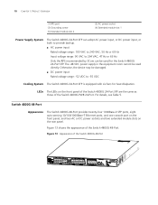
... be damaged. ■ DC power input Rated voltage range: -52 VDC to 264 VAC, 47 Hz or 63 Hz Only the RPS recommended by 3Com can adopt AC power input, or DC power input, or both to provide backup. ■ AC power input Rated voltage range: 100 VAC to.... The -48 VDC power supply in the equipment room cannot be used for heat dissipation. Figure 13 shows the appearance of the Switch 4800G 48-Port Figure 13 Appearance of the Switch 4800G 48-Port. 18 CHAPTER 1: PRODUCT OVERVIEW (1) RPS port (3) Grounding screw (5) Extended module slot 2 (2) AC power socket (4) Extended module slot 1 ...
... be damaged. ■ DC power input Rated voltage range: -52 VDC to 264 VAC, 47 Hz or 63 Hz Only the RPS recommended by 3Com can adopt AC power input, or DC power input, or both to provide backup. ■ AC power input Rated voltage range: 100 VAC to.... The -48 VDC power supply in the equipment room cannot be used for heat dissipation. Figure 13 shows the appearance of the Switch 4800G 48-Port Figure 13 Appearance of the Switch 4800G 48-Port. 18 CHAPTER 1: PRODUCT OVERVIEW (1) RPS port (3) Grounding screw (5) Extended module slot 2 (2) AC power socket (4) Extended module slot 1 ...
Getting Started Guide
Page 19
...; DC power input Rated voltage range: -48 VDC to -60 VDC Input voltage range: -36 VDC to -72 VDC Cooling System The Switch 4800G 48-Port is equipped with six fans (four for the system, and one for each power module) for extended module slot 1 (10) Mode... LED Rear Panel Figure 15 Rear panel of the Switch 4800G 48-Port (1) (2) (3) (4) (5) (1) Grounding screw (3) Power module slot 2 (5) Extended module slot 2 (2) Power module slot 1 (4) Extended module slot 1 Power System The Switch 4800G 48-Port can switch the Mode LED display mode between speed and duplex by pressing the ...
...; DC power input Rated voltage range: -48 VDC to -60 VDC Input voltage range: -36 VDC to -72 VDC Cooling System The Switch 4800G 48-Port is equipped with six fans (four for the system, and one for each power module) for extended module slot 1 (10) Mode... LED Rear Panel Figure 15 Rear panel of the Switch 4800G 48-Port (1) (2) (3) (4) (5) (1) Grounding screw (3) Power module slot 2 (5) Extended module slot 2 (2) Power module slot 1 (4) Extended module slot 1 Power System The Switch 4800G 48-Port can switch the Mode LED display mode between speed and duplex by pressing the ...
Getting Started Guide
Page 20
... is in the power module slot and the output is output. 20 CHAPTER 1: PRODUCT OVERVIEW Table 6 Description of LEDs on the front panel of the Switch 4800G 48-Port LED Mode LED System power LED Mark Status Mode Speed Solid green Duplex Solid yellow SYS Solid green Flashing green (1 Hz) Solid red... slot 2 PWR2 Solid green Solid yellow OFF Module LED MOD Solid green Flashing yellow OFF Description Rate of the port Duplex of the port The switch is installed. No power module is installed in the power module slot but no power is output. A power module is installed in the power ...
... is in the power module slot and the output is output. 20 CHAPTER 1: PRODUCT OVERVIEW Table 6 Description of LEDs on the front panel of the Switch 4800G 48-Port LED Mode LED System power LED Mark Status Mode Speed Solid green Duplex Solid yellow SYS Solid green Flashing green (1 Hz) Solid red... slot 2 PWR2 Solid green Solid yellow OFF Module LED MOD Solid green Flashing yellow OFF Description Rate of the port Duplex of the port The switch is installed. No power module is installed in the power module slot but no power is output. A power module is installed in the power ...
Getting Started Guide
Page 21
...is present. The port operates in the full duplex mode. A 1000 Mbps link is being received or sent, the LED flashes at a high frequency. Switch 4800G 48-Port 21 Table 6 Description of LEDs on the LED. When data is present. When data is only one unit. The LED flashes the POST... test ID of the Switch 4800G 48-Port LED 7-segment digital LED Mark Status Unit POST running Description The power LED flashes green. Cluster status Solid green Auto-sensing - 10/100...
...is present. The port operates in the full duplex mode. A 1000 Mbps link is being received or sent, the LED flashes at a high frequency. Switch 4800G 48-Port 21 Table 6 Description of LEDs on the LED. When data is present. When data is only one unit. The LED flashes the POST... test ID of the Switch 4800G 48-Port LED 7-segment digital LED Mark Status Unit POST running Description The power LED flashes green. Cluster status Solid green Auto-sensing - 10/100...
