
Quick Start Guide
Page 1
... Installation • Step 3: Connecting External Antennas • Step 4: Mounting the Access Point • Step 5: Connecting the Access Point to the network. Three WLAN switch devices can be connected to the access point: • 3Com PoE Injector • 3Com 4400PWR PoE Switch • 3Com Multi-port PoE power supply • 3Com 5500 Series PoE capable switches • 3Com WX1200 • 3Com WXR100 About This Guide This Quick Start Guide describes the basic installation of the access point. All configuration for use with a 3Com Wireless LAN Switch, and requires hardware installation...
... Installation • Step 3: Connecting External Antennas • Step 4: Mounting the Access Point • Step 5: Connecting the Access Point to the network. Three WLAN switch devices can be connected to the access point: • 3Com PoE Injector • 3Com 4400PWR PoE Switch • 3Com Multi-port PoE power supply • 3Com 5500 Series PoE capable switches • 3Com WX1200 • 3Com WXR100 About This Guide This Quick Start Guide describes the basic installation of the access point. All configuration for use with a 3Com Wireless LAN Switch, and requires hardware installation...

Quick Start Guide
Page 2
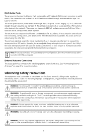
...-0040 3Com AP3750 Managed Access Point Features Diameter 16.76 cm (6.6 inches) TM Height 4.69 cm (1.85 inches) Kensington security slot External antenna connectors 802.11b/g 802.11a Unlock 840-9502-0007 RJ-45 ports Port 2 Port 1 Kensington Security Slot The access point has a slot for attachment of the access point there is a lock hole. Lock and Unlock Holes On one side of a Kensington security cable. CAUTION...
...-0040 3Com AP3750 Managed Access Point Features Diameter 16.76 cm (6.6 inches) TM Height 4.69 cm (1.85 inches) Kensington security slot External antenna connectors 802.11b/g 802.11a Unlock 840-9502-0007 RJ-45 ports Port 2 Port 1 Kensington Security Slot The access point has a slot for attachment of the access point there is a lock hole. Lock and Unlock Holes On one side of a Kensington security cable. CAUTION...
Quick Start Guide
Page 3
... exposed body part while the device's radio antenna is safety certified according to UL, CSA, IEC, or other port can reboot using the other device in this document refer to power supply in the network. See "Connecting External Antennas" on port 1 first. WARNING: Do not hold any radio device so that is transmitting. 3 The access point receives power and data through an intermediate Layer 2 or Layer 3 network. Use a Category 5 (Cat 5) cable with straight...
... exposed body part while the device's radio antenna is safety certified according to UL, CSA, IEC, or other port can reboot using the other device in this document refer to power supply in the network. See "Connecting External Antennas" on port 1 first. WARNING: Do not hold any radio device so that is transmitting. 3 The access point receives power and data through an intermediate Layer 2 or Layer 3 network. Use a Category 5 (Cat 5) cable with straight...

Quick Start Guide
Page 4
... routed through signaling is installed at the site before inserting a cable into the access point. 1 Unpacking the Access Point Make sure that standard Category 5 cable with the access point: • Mounting Kit: • One universal mounting bracket (attached to connect the power (if using a wireless device in a properly installed enclosure. Additional MAC address labels are included with straight-through the mounting bracket • Power Power must be supplied via an 802.3af Power Over Ethernet...
... routed through signaling is installed at the site before inserting a cable into the access point. 1 Unpacking the Access Point Make sure that standard Category 5 cable with the access point: • Mounting Kit: • One universal mounting bracket (attached to connect the power (if using a wireless device in a properly installed enclosure. Additional MAC address labels are included with straight-through the mounting bracket • Power Power must be supplied via an 802.3af Power Over Ethernet...
Quick Start Guide
Page 5
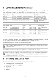
... access point is supplied with the access point. The tables below list the external antenna and cable models that your application allows. Connectorsa SMA (male) to N-type (male) SMA (male) to N-type (male) SMA (male) to the access point before connecting the Category 5 Ethernet cable. This ensures that they operate in both 2.4GHz and 5GHz spectra. For installation instructions, see the documentation that is connected to the network. 4 Mounting the Access Point The access point can use...
... access point is supplied with the access point. The tables below list the external antenna and cable models that your application allows. Connectorsa SMA (male) to N-type (male) SMA (male) to N-type (male) SMA (male) to the access point before connecting the Category 5 Ethernet cable. This ensures that they operate in both 2.4GHz and 5GHz spectra. For installation instructions, see the documentation that is connected to the network. 4 Mounting the Access Point The access point can use...

Quick Start Guide
Page 6
.... Cable Requirement The Ethernet ports on the access point cannot accept a Category 5 cable that are 23.9 mm (15/16 inches) wide. Drop Ceiling Tiles" on the access point. The RJ-45 connector on the cable will not seat properly in the figure below. Flush Ceiling Tiles This procedure applies to "Suspended Ceiling Installation - TM AP37M50obacilciteyss point point MoMuonutintgintgemplate template MouMntoinugntbinragcket bracket 1 Use the...
.... Cable Requirement The Ethernet ports on the access point cannot accept a Category 5 cable that are 23.9 mm (15/16 inches) wide. Drop Ceiling Tiles" on the access point. The RJ-45 connector on the cable will not seat properly in the figure below. Flush Ceiling Tiles This procedure applies to "Suspended Ceiling Installation - TM AP37M50obacilciteyss point point MoMuonutintgintgemplate template MouMntoinugntbinragcket bracket 1 Use the...

Quick Start Guide
Page 7
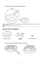
3 Attach the mounting bracket to the mounting bracket Lock T-bar TM 7 840-9502-0006 TM Universal mounting bracket T-bar Port connector opening Universal mounting bracket T-bar 840-9502-0005 Port connector opening (Viewed from above ceiling tiles, looking down.) 4 If you are using an external antenna, insert the antenna cable into the antenna connector on the access point. 5 Insert the Category 5 cable through the port connector opening in the mounting bracket, then plug the cable into the access point. 840-9502-0002 TM 6 Attach the access point to the T-bar clamp.
3 Attach the mounting bracket to the mounting bracket Lock T-bar TM 7 840-9502-0006 TM Universal mounting bracket T-bar Port connector opening Universal mounting bracket T-bar 840-9502-0005 Port connector opening (Viewed from above ceiling tiles, looking down.) 4 If you are using an external antenna, insert the antenna cable into the antenna connector on the access point. 5 Insert the Category 5 cable through the port connector opening in the mounting bracket, then plug the cable into the access point. 840-9502-0002 TM 6 Attach the access point to the T-bar clamp.

Quick Start Guide
Page 8
... can also use an external antenna for the 802.11b/g or 802.11a radio, install the antenna at least 20 cm from the access point. T-bar T-bar clamp halves Slide together 840-9502-0003 23.9-mm (15/16-in) or 14.2-mm (9/16-in ) T-bar 8 Drop Ceiling Tiles This procedure applies to use this procedure for the Category 5 cable. 2 Install the...
... can also use an external antenna for the 802.11b/g or 802.11a radio, install the antenna at least 20 cm from the access point. T-bar T-bar clamp halves Slide together 840-9502-0003 23.9-mm (15/16-in) or 14.2-mm (9/16-in ) T-bar 8 Drop Ceiling Tiles This procedure applies to use this procedure for the Category 5 cable. 2 Install the...

Quick Start Guide
Page 9
... down.) Universal mounting bracket T-bar 5 If you are using an external antenna, insert the antenna cable into the antenna connector on the access point. 6 Insert the Category 5 cable through the port connector opening 840-9502-0012 T-bar clamps (attached to the T-bar clamp. bar Port connector opening in the mounting bracket, then plug the cable into the access point. 840-9502-0002 TM 9 Universal mounting bracket T-
... down.) Universal mounting bracket T-bar 5 If you are using an external antenna, insert the antenna cable into the antenna connector on the access point. 6 Insert the Category 5 cable through the port connector opening 840-9502-0012 T-bar clamps (attached to the T-bar clamp. bar Port connector opening in the mounting bracket, then plug the cable into the access point. 840-9502-0002 TM 9 Universal mounting bracket T-
Quick Start Guide
Page 10
Junction Box Installation TM Mobility AP375p0oaincctess point MMoouunnttiningg bbrraacckkeett MMoouunnttiinngg hhaarrddwwaarree 1 Remove the mounting bracket from the access point. 7 Attach the access point to use an external antenna for the 802.11b/g or 802.11a radio, install the antenna at least 20 cm from the access point. 840-9502-0011 840-9502-0008 10 Lock T-bar 840-9502-0006 TM TM CAUTION: If you plan to the mounting bracket.
Junction Box Installation TM Mobility AP375p0oaincctess point MMoouunnttiningg bbrraacckkeett MMoouunnttiinngg hhaarrddwwaarree 1 Remove the mounting bracket from the access point. 7 Attach the access point to use an external antenna for the 802.11b/g or 802.11a radio, install the antenna at least 20 cm from the access point. 840-9502-0011 840-9502-0008 10 Lock T-bar 840-9502-0006 TM TM CAUTION: If you plan to the mounting bracket.

Quick Start Guide
Page 11
840-9502-0017 2 Attach the bracket to the mounting bracket. Junction box Port connector opening 3 If you plan to use an external antenna for the 802.11b/g or 802.11a radio, install the antenna at least 20 cm from the access point. 11 TM 840-9502-0062 TM Lock CAUTION: If you are using an external antenna, insert the antenna cable into the antenna connector on the access point. 4 Plug the Category 5 cable into the access point and attach the access point to the junction box.
840-9502-0017 2 Attach the bracket to the mounting bracket. Junction box Port connector opening 3 If you plan to use an external antenna for the 802.11b/g or 802.11a radio, install the antenna at least 20 cm from the access point. 11 TM 840-9502-0062 TM Lock CAUTION: If you are using an external antenna, insert the antenna cable into the antenna connector on the access point. 4 Plug the Category 5 cable into the access point and attach the access point to the junction box.
Quick Start Guide
Page 12
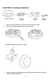
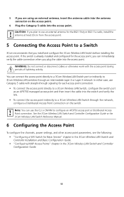
TM 4 If you are using an external antenna, insert the antenna cable into the antenna connector on the access point. 12 840-9502-0015 Solid Wall or Ceiling Installation TM AP37M5o0baiclictyess point point MoMuonutnintging temtepmlpaltaete MMouonutnintigng brbarcakceket t MMoouunnttiinngg hhaarrddwwaarree 1 Use the mounting template to cut a hole for the Category 5 cable. 2 Remove the mounting bracket from the access point. 840-9502-0011 840-9502-0008 3 Attach the bracket to the wall or ceiling.
TM 4 If you are using an external antenna, insert the antenna cable into the antenna connector on the access point. 12 840-9502-0015 Solid Wall or Ceiling Installation TM AP37M5o0baiclictyess point point MoMuonutnintging temtepmlpaltaete MMouonutnintigng brbarcakceket t MMoouunnttiinngg hhaarrddwwaarree 1 Use the mounting template to cut a hole for the Category 5 cable. 2 Remove the mounting bracket from the access point. 840-9502-0011 840-9502-0008 3 Attach the bracket to the wall or ceiling.
Quick Start Guide
Page 13
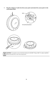
Cable TM Universal mounting bracket TM Lock CAUTION: If you plan to the mounting bracket. 840-9502-0016 TM 5 Plug the Category 5 cable into the access point and attach the access point to use an external antenna for the 802.11b/g or 802.11a radio, install the antenna at least 20 cm from the access point. 13 840-9502-0062
Cable TM Universal mounting bracket TM Lock CAUTION: If you plan to the mounting bracket. 840-9502-0016 TM 5 Plug the Category 5 cable into the access point and attach the access point to use an external antenna for the 802.11b/g or 802.11a radio, install the antenna at least 20 cm from the access point. 13 840-9502-0062

Quick Start Guide
Page 14
RRuubbbbeerr ffeeeett 840-9502-0008 840-9502-0011 2 Reverse the bracket and reattach it to the access point. 840-9502-0061 840-9502-0013 3 Attach the rubber feet. 4 Turn the access point over and place it on the table. 14 Tabletop Installation TM AP3M75o0bailictcyess point point MMouonutnintigng brbarcakckeett 1 Remove the mounting bracket from the access point.
RRuubbbbeerr ffeeeett 840-9502-0008 840-9502-0011 2 Reverse the bracket and reattach it to the access point. 840-9502-0061 840-9502-0013 3 Attach the rubber feet. 4 Turn the access point over and place it on the table. 14 Tabletop Installation TM AP3M75o0bailictcyess point point MMouonutnintigng brbarcakckeett 1 Remove the mounting bracket from the access point.
Quick Start Guide
Page 15
...Layer 3 network. CAUTION: If you can use an external antenna for Basic Service" chapter in the 3Com Wireless LAN Switch and Controller Installation and Basic Configuration Guide. • "Configuring MAP Access Points" chapter in the 3Com Wireless LAN Switch and Controller Configuration Guide. 15 If the switch is already installed and configured for each access point connection. • To connect the access point directly to a 3Com Wireless LAN Switch, configure the switch port as an AP3750 managed access point and then insert the cable into the switch and verify the link. •...
...Layer 3 network. CAUTION: If you can use an external antenna for Basic Service" chapter in the 3Com Wireless LAN Switch and Controller Installation and Basic Configuration Guide. • "Configuring MAP Access Points" chapter in the 3Com Wireless LAN Switch and Controller Configuration Guide. 15 If the switch is already installed and configured for each access point connection. • To connect the access point directly to a 3Com Wireless LAN Switch, configure the switch port as an AP3750 managed access point and then insert the cable into the switch and verify the link. •...
Quick Start Guide
Page 16
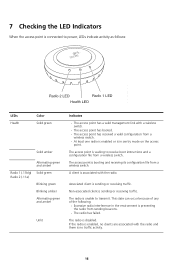
... Radio 1 (.11b/g) Solid green Radio 2 (.11a) Blinking green Blinking amber Alternating green and amber Unlit Indicates • The access point has a valid management link with the radio. This state can occur because of any of the following: • Excessive radio interference in the environment is preventing the radio from a wireless switch. • At least one radio is enabled or is in sentry mode on the access point. If the radio is enabled, no clients...
... Radio 1 (.11b/g) Solid green Radio 2 (.11a) Blinking green Blinking amber Alternating green and amber Unlit Indicates • The access point has a valid management link with the radio. This state can occur because of any of the following: • Excessive radio interference in the environment is preventing the radio from a wireless switch. • At least one radio is enabled or is in sentry mode on the access point. If the radio is enabled, no clients...
Quick Start Guide
Page 17
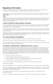
... booklet prepared by 3Com could void the user's authority to Part 15 of connecting cables and equipment other antenna or transmitter. This device must not be co-located or operated in conjunction with FCC radio-frequency exposure guidelines for any user serviceable components. These radar...instructions, it does not emit RF field in excess of the 5.25 to 5.35 GHz and 5.65 to -antenna distance of the U.S. Note: This product contains encryption. The installer of this 3Com AP3750 Managed Access Point (3CRWX375075A), or the substitution or attachment of FCC Rules. consult Safety Code...
... booklet prepared by 3Com could void the user's authority to Part 15 of connecting cables and equipment other antenna or transmitter. This device must not be co-located or operated in conjunction with FCC radio-frequency exposure guidelines for any user serviceable components. These radar...instructions, it does not emit RF field in excess of the 5.25 to 5.35 GHz and 5.65 to -antenna distance of the U.S. Note: This product contains encryption. The installer of this 3Com AP3750 Managed Access Point (3CRWX375075A), or the substitution or attachment of FCC Rules. consult Safety Code...
Quick Start Guide
Page 18
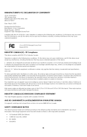
... term "IC" before the equipment certification number only signifies that the Product: Brand Name: 3Com Corporation Model Number: AP3750 Equipment Type: Managed Access Point Complies with and/or damage this device. Pour empêcher que cet appareil cause du brouillage au service faisant l'objet d'une licence, il doit... radio interference to licensing. High power radars are allocated as primary users of Industry Canada. INDUSTRY CANADA (IC) EMISSIONS COMPLIANCE STATEMENT This Class B digital apparatus complies with RSS 210 of the 5.25 to 5.35 GHz and 5.65 to 5.85 GHz bands....
... term "IC" before the equipment certification number only signifies that the Product: Brand Name: 3Com Corporation Model Number: AP3750 Equipment Type: Managed Access Point Complies with and/or damage this device. Pour empêcher que cet appareil cause du brouillage au service faisant l'objet d'une licence, il doit... radio interference to licensing. High power radars are allocated as primary users of Industry Canada. INDUSTRY CANADA (IC) EMISSIONS COMPLIANCE STATEMENT This Class B digital apparatus complies with RSS 210 of the 5.25 to 5.35 GHz and 5.65 to 5.85 GHz bands....
Quick Start Guide
Page 20
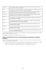
... Direktyvos nuostatas. Šiuo 3Com Corporation deklaruoja, kad šis only permitted using the 2.4GHz band: Channels 1 - 13, except where noted below. • In Italy the end-user must apply for a license from the Product Support web page for the AP3750 (3CRWX375075A) at http://support.3com.com/doc/AP3750_EU_DOC.pdf EUROPE - Käesolevaga kinnitab 3Com Corporation seadme RLAN device vastavust direktiivi 1999/5/EÜ...
... Direktyvos nuostatas. Šiuo 3Com Corporation deklaruoja, kad šis only permitted using the 2.4GHz band: Channels 1 - 13, except where noted below. • In Italy the end-user must apply for a license from the Product Support web page for the AP3750 (3CRWX375075A) at http://support.3com.com/doc/AP3750_EU_DOC.pdf EUROPE - Käesolevaga kinnitab 3Com Corporation seadme RLAN device vastavust direktiivi 1999/5/EÜ...
Quick Start Guide
Page 21
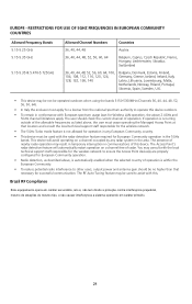
...channel occupied by any European Community country. • This device must apply for Wireless LAN operation, the above , is automatically enabled when the selected country of operation is occurring outside of nearby radar operation may consult with this. The RF Auto-Tuning feature may be not be used... the local technical support staff responsible for the wireless network to ensure the Access Point device(s) are properly configured for European Community operation. • Radio detection, as listed above, the user must cease operating the Managed Access Point at that necessary for...
...channel occupied by any European Community country. • This device must apply for Wireless LAN operation, the above , is automatically enabled when the selected country of operation is occurring outside of nearby radar operation may consult with this. The RF Auto-Tuning feature may be not be used... the local technical support staff responsible for the wireless network to ensure the Access Point device(s) are properly configured for European Community operation. • Radio detection, as listed above, the user must cease operating the Managed Access Point at that necessary for...


