Sony HCD-SH2000 Support Question
Sony HCD-SH2000 Support Question
Find answers below for this question about Sony HCD-SH2000.Need a Sony HCD-SH2000 manual? We have 1 online manual for this item!
Question posted by vuser707 on December 20th, 2014
When I Connect My Sony Hifi Hcd-sh2000 To The Mains, The Circuit Breaker On The
The person who posted this question about this Sony product did not include a detailed explanation. Please use the "Request More Information" button to the right if more details would help you to answer this question.
Current Answers
Related Sony HCD-SH2000 Manual Pages
Service Manual - Page 1
...African model
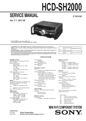
MINI HI-FI COMPONENT SYSTEM
9-890-576-02 2011I08-1 © 2011.09
Sony Corporation
Published by Sony EMCS (Malaysia) PG ...HCD-SH2000
SERVICE MANUAL
E Model
Ver. 1.1 2011.09
• HCD-SH2000 is the tuner, USB, CD and amplifier section in FST-SH2000/LBT-SH2000.
• "WALKMAN" and "WALKMAN" logo are registered trademarks of Sony Corporation. • MPEG Layer-3 audio...
Service Manual - Page 2
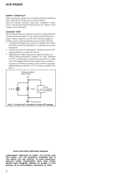
...' instructions to use these instruments. 2.
HCD-SH2000
SAFETY CHECK-OUT After correcting the original service problem, perform the following safety check before releasing the set to the customer: Check the antenna terminals, metal trim, "metallized" knobs, screws, and all other exposed metal parts for this job. 3. SAFETY-RELATED COMPONENT WARNING! A commercial leakage tester...
Service Manual - Page 3
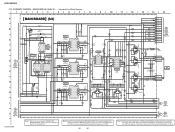
... - Schematic Diagram - Schematic Diagram - Schematic Diagram - HCD-SH2000
TABLE OF CONTENTS
1. DAMP Board, MAIN Board 10 2-9. Schematic Diagram - Printed Wiring Boards - Schematic Diagram - CD MECHANISM DECK BLOCK (2 9 2-8. PANEL, POWER SUPPLY Section - . 18 5-5. Schematic Diagram - Schematic Diagram - DAMP Board (Component Side 37 5-23. DAMP Board (4/4 42 5-28...
Service Manual - Page 14
HCD-SH2000
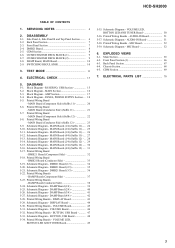
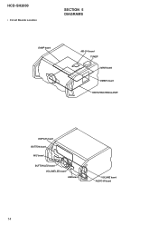
• Circuit Boards Location
SECTION 5 DIAGRAMS
DAMP board
MS-214 board TUNER MAIN board
DMB21 board SWITCHING REGULATOR
DISPLAY board BUTTON board
MIC board
BUTTON LED board VOLUME LED board USB board
VOLUME board AUDIO-IN board
14
Service Manual - Page 20

... 37)
J
HCD-SH2000
20
20
Note: Refer to the servicing notes "MAIN BOARD DISCRIMINATION" (page 5) for Circuit Boards Location. • : Uses unleaded solder.
1
2
3
4
5
6
7
8
9
10
11
12
13
14
15
A
B
TUNER
J BOARD
CN1601 (Page 49)
C
(".&
"6%*0 */
-
3
D
%7%4"5
"6%*0 */
-3
E
-
F
-&%
41&",&3
3
G
H
I
F700
3
1
3
1
J500
MAIN BOARD
(Component side)
DMB21...
Service Manual - Page 21
HCD-SH2000
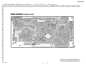
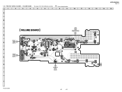
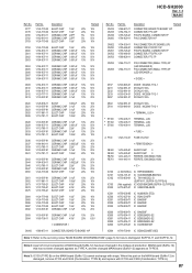
5-6. PRINTED WIRING BOARDS - MAIN BOARD (Conductor Side) (Suffix-11) - • See page 14 for Circuit Boards Location. • : Uses unleaded solder.
1
2
3
4
5
6
7
8
9
10
11
12
13
14
15
A
B
MAIN BOARD (Conductor side)
C
D
E
F
G
H
11 1-883-863- (11)
I
J
HCD-SH2000
21
21
Note: Refer to the servicing notes "MAIN BOARD DISCRIMINATION" (page 5) for ...
Service Manual - Page 22

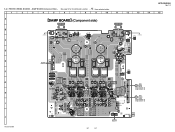
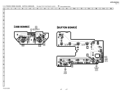
...-863- MAIN BOARD (Component Side) (Suffix-12) - • See page 14 for how to the servicing notes "MAIN BOARD DISCRIMINATION" (page 5) for Circuit Boards Location. • : Uses unleaded solder.
1
2
3
4
5
6
7
8
9
10
11
12
13
14
15
A
MAIN BOARD (Component side)
B
TUNER
J BOARD
CN1601 (Page 49)
C
(".&
"6%*0 */
-3
D
%7%4"5
"6%*0 */
-3
E
- HCD-SH2000
5-7.
Service Manual - Page 23

... (Conductor Side) (Suffix-12) - • See page 14 for Circuit Boards Location. • : Uses unleaded solder.
1
2
3
4
5
6
7
8
9
10
11
12
13
14
15
A
B
MAIN BOARD (Conductor side)
C
D
E
F
G
H
12 1-883-863- (12)
I
J
HCD-SH2000
23
23
Note: Refer to the servicing notes "MAIN BOARD DISCRIMINATION" (page 5) for how to distinguish SUFFIX-11 and SUFFIX-12. PRINTED...
Service Manual - Page 30
...
CN705 3P
JL401
1 13.5V
JL402
2 RED_LED
- Note 2: A part of circuit composition of production. OUTPUT 7
4.5
4.5
3 INPUT+ INPUT- 6 4.5
4 GND...DRIVER
3.2
C804 1000p 50V C809
23
24
25
MAIN
6 26
BOARD
(4/4)
27
(Page 31)
28
29
30
MAIN
7 BOARD
31
(4/4)
32
(Page 31)
HCD-SH2000
Note 1: Refer to the servicing notes "MAIN BOARD DISCRIMINATION" (page 5) for IC Block Diagrams....
Service Manual - Page 32

... is damaged, exchange the entire mounted board. DMB21 BOARD (Component Side) - • See page 14 for Circuit Boards Location. • : Uses unleaded solder.
1
2
3
4
5
6
7
8
9
10
11
12
13
14
15
A B C D E F G H I
J
HCD-SH2000
DMB21 BOARD (Component side) NC
(CHASSIS)
MAIN
I BOARD
CN702 (Page 20) (Suffix 11) (Page 22) (Suffix 12)
MAIN
F BOARD
CN701 (Page 20) (Suffix 11) (Page 22...
Service Manual - Page 37
...8226; See page 14 for Circuit Boards Location. • : Uses unleaded solder.
1
2
3
4
5
6
7
8
9
10
11
12
13
14
A B C D E F G H I
J
HCD-SH2000
DAMP BOARD (Component side)
LOW SPEAKER
(CHASSIS)
...BOARDS - MAIN
G BOARD CN102 (Page 20) (Suffix 11) (Page 22) (Suffix 12)
MAIN
B BOARD CN100 (Page 20) (Suffix 11) (Page 22) (Suffix 12)
12 (12)
SWITCHING REGULATOR
37
37
HCD-SH2000
Ver. ...
Service Manual - Page 45
HCD-SH2000
Ver. 1.1
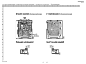
5-30. PRINTED WIRING BOARDS - VOLUME BOARD - • See page 14 for Circuit Boards Location. • : Uses unleaded solder.
1
2
3
4
5
6
7
8
9
10
11
12
13
14
15
A
B
R1026
C
VOLUME BOARD
MAIN BOARD CN105 (Page 20) (Suffix 11) (Page 22) (Suffix 12)
S1013
A
EJECT
D
JL1008 JL1010 JL1012 JL1014 JL1017 JL1020
JL1079 JR JR1040
JL1064
JL1097
JL1003...
Service Manual - Page 47
...BOARD CN1280 (Page 49)
14
31
O
VOLUME BOARD NO1001 (Page 45)
J
HCD-SH2000
47
47 HCD-SH2000
Ver. 1.1
5-32. JL1280 JL1281
S1261 JL1277
R1267
JL1252 JR JR1201 JL1253 JL1255
D1256..., USB BOARD - • See page 14 for Circuit Boards Location. • : Uses unleaded solder.
1
2
3
4
5
6
7
8
9
10
11
12
13
14
15
A
B
C
USB BOARD
MAIN BOARD
CN300
C (Page 20) (Suffix 11) (Page...
Service Manual - Page 49
...HCD-SH2000
Ver. 1.1
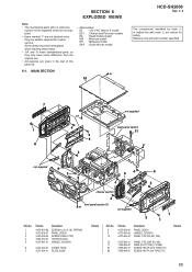
5-34. VOLUME LED, BUTTON LED AND TUNER BOARD - • See page 14 for Circuit Boards Location. • : Uses unleaded solder.
1
2
3
4
5
6
7
8
9
10
11
12
13
14
15
A
B
TUNER BOARD (Component...
11
20
C1603
C1613
JL1604
R1609
X1601
1
2
JL1606
JL1607
JL1602
C1604 C1605
MAIN
JL1601
CN1601
F
J BOARD
JL1605
JL1603
CN703
6
(Page 20) (Suffix 11...
Service Manual - Page 51

•
: Uses unleaded solder.
5-36. SCHEMATIC DIAGRAM -
AUDIO-IN BOARD - • See page 14 for Circuit Boards Location.
5-37. HCD-SH2000
Ver. 1.1
1
2
3
4
5
6
1
2
3
4
5
6
7
8
A
A
B
B
C
D
AUDIO-IN BOARD
1-883-868- 13
(13)
JL1202
3 1 C1201 C1200 R1201 R1200
JL1205
E
JL1200
H
R1204 R1205
MAIN BOARD
JL1204 JL1203
C1203 R1203
C1205
R1207
C1204
8 R1202
...
Service Manual - Page 53

• Waveforms - DMB21 Board -
5 IC101 9 (XTALI)
133.3 mVp-p 26.99 MHz 125 mV/DIV, 37 nsec/DIV
6 IC101
Service Manual - Page 65
MAIN SECTION
#1
10
HCD-SH2000
Ver. 1.1
The components identified by mark 0 or dotted line with mark 0 are given in the ...SIDE B SCREW (CASE 3 TP2) +BVTP2.6 (3CR) HANDLE, COVER B
6
4-291-803-01 COVER, HOLE
7
4-277-991-01 PLATE, SONY
Remark
Ref. Some delay should be anticipated when ordering these items. • -XX and -X mean standardized parts, so they are seldom required for ...
Service Manual - Page 79

...218-965-11 METAL CHIP 10K
5% 1/16W 5% 1/16W 5% 1/16W
5% 1/16W 5% 1/16W 5% 1/16W
< COMPOSITION CIRCUIT BLOCK >
RB105 RB106 RB107 RB108 RB111
1-234-400-21 1-234-400-21 1-234-400-21 1-234-400-21 1-234-... 10% 25V
Note 1: Refer to the servicing notes "MAIN BOARD DISCRIMINATION" (page 5) for how to distinguish SUFFIX-11 and SUFFIX-12. Part No. HCD-SH2000
Ver. 1.1
DMB21 MAIN
Ref.
Part No.
Service Manual - Page 80

...the servicing notes "MAIN BOARD DISCRIMINATION" (page 5) for how to distinguish SUFFIX-11 and SUFFIX-12. When this part on the MAIN board (Suffi... 100uF 20% 16V
Ref. HCD-SH2000
Ver. 1.1
MAIN
Ref.
MAIN board (Suffix-12) that has not been changed ...of MAIN board (Suffix-12) has been changed MAIN board (Suffix-12) appears as TYPE B. Note 3: C242 (TYPE B) on the MAIN board...
Service Manual - Page 81
... damaged, remove IC103 and C242 (Combination: TYPE B) and replace with single. HCD-SH2000
Ver. 1.1
MAIN
Ref.
CN102 CN105 CN106 CN300
Part No.
1-568-673-11 1-784-784-... to the servicing notes "MAIN BOARD DISCRIMINATION" (page 5) for how to distinguish SUFFIX-11 and SUFFIX-12. No. Note 2: A part of circuit composition of MAIN board (Suffix-12) has been changed MAIN board (Suffix-12...
Similar Questions

Hcd Sh2000 Sony
I have HCD SH 2000 it's has no audio out in any Chanel ( first it was on protection mode then now it...
I have HCD SH 2000 it's has no audio out in any Chanel ( first it was on protection mode then now it...
(Posted by Sehar517 1 year ago)

My Sony Hcd-sh2000 Does Not Switch On
Sony HCD-SH2000 does not switch ON but when the mains supply is unplugged the standby light flashes ...
Sony HCD-SH2000 does not switch ON but when the mains supply is unplugged the standby light flashes ...
(Posted by allieukamaraak 3 years ago)

Sony Radio Circuit Hcd-sh2000
Good Dayi Am Interesting In Buying A Radio Circuit Hcd-sh2000 (only) And Whats The Price?
Good Dayi Am Interesting In Buying A Radio Circuit Hcd-sh2000 (only) And Whats The Price?
(Posted by diel060781 4 years ago)

Parts Of Sony Hcd Sh2000
Dear Sir.I would like to ask you regarding Sony HCD-SH2000 electronic parts number Main Board. Damp...
Dear Sir.I would like to ask you regarding Sony HCD-SH2000 electronic parts number Main Board. Damp...
(Posted by rizwanbutt94 6 years ago)

Can You Connect A Cassette Player/turntable To This? (audio Input).
(Posted by blloyd66 11 years ago)