Sony HCD-SH2000 Support Question
Sony HCD-SH2000 Support Question
Find answers below for this question about Sony HCD-SH2000.Need a Sony HCD-SH2000 manual? We have 1 online manual for this item!
Question posted by preddierandy on April 4th, 2015
Where Can I Purchase Parts For My Set
The person who posted this question about this Sony product did not include a detailed explanation. Please use the "Request More Information" button to the right if more details would help you to answer this question.
Current Answers
Answer #1: Posted by BusterDoogen on April 4th, 2015 10:14 AM
BusterDoogen

Member since:
October 30th, 2011 Points: 28,565,397

Member since:
October 30th, 2011 Points: 28,565,397
Go here for some parts. You might have some success by checking with
1-800-488-SONY (7669)
Mon-Fri 8:00AM - 12:00AM ET
Sat-Sun 10:00AM - 9:00PM ET
I hope this is helpful to you!
Please respond to my effort to provide you with the best possible solution by using the "Acceptable Solution" and/or the "Helpful" buttons when the answer has proven to be helpful. Please feel free to submit further info for your question, if a solution was not provided. I appreciate the opportunity to serve you!
Related Sony HCD-SH2000 Manual Pages
Service Manual - Page 1
... 500 W + 500 W (per channel at 4 Ω, 100 Hz) Inputs PC (AUDIO IN) L/R, TV (AUDIO IN) L/R, DVD/SAT (AUDIO IN) L/R, GAME (AUDIO IN) L/R Voltage 2 V, impedance 47 kΩ MIC Sensitivity 1 mV, impedance 10 k&#...COMPONENT SYSTEM
9-890-576-02 2011I08-1 © 2011.09
Sony Corporation
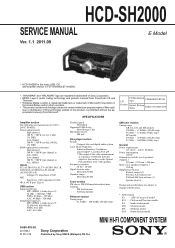
Published by Sony EMCS (Malaysia) PG Tec HCD-SH2000
SERVICE MANUAL
E Model
Ver. 1.1 2011.09
• HCD-SH2000...
Service Manual - Page 2
... this job. 3.
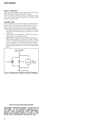
SAFETY-RELATED COMPONENT WARNING! A battery-operated AC milliammeter. REPLACE THESE COMPONENTS WITH SONY PARTS WHOSE PART NUMBERS APPEAR AS SHOWN IN THIS MANUAL OR IN SUPPLEMENTS PUBLISHED BY SONY.
2 HCD-SH2000
SAFETY CHECK-OUT After correcting the original service problem, perform the following safety check before releasing the set to chassis, must have a 2V AC...
Service Manual - Page 3
...52
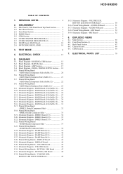
6. ELECTRICAL PARTS LIST 70
3 SERVICING NOTES 4
2. Block Diagram - MAIN Board (3/4) (Suffix 11) -... 26 5-12. Schematic Diagram - DMB21 Board (Component Side 32 5-18...DMB21 Board (2/3 35 5-21. AUDIO-IN Board 51 5-37. DISPLAY Board 44 5-30. MAIN Board (2/4) (Suffix 12) - .. 29 5-15. HCD-SH2000
TABLE OF CONTENTS
1. AUDIO-IN Board 51 5-38. Front...
Service Manual - Page 4
... caution not to let solder bridges occur such as to be set to about 40 °C higher
than those specified ...audio data.
PART No. A Multi Session disc is claassified as a single session.
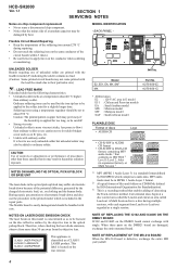
NOTE OF REPLACEMENT OF THE MS-214 BOARD When the MS-214 board is a standard format defined by heat. HCD-SH2000
Ver. 1.1
SECTION 1 SERVICING NOTES
Notes on chip component...
Service Manual - Page 5
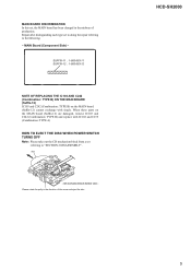
... rotate the pully in the midway of the arrow and eject the disc. HCD-SH2000
5
disc
- Repair after distinguishing each type set , the MAIN board has been changed in the direction of production. MAIN Board (Component Side) - MAIN BOARD DISCRIMINATION In this set to doing the repair referring to "SECTION 2 DISASSEMBLY". CD mechanism block bottom...
Service Manual - Page 6
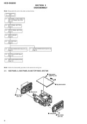
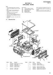
... BLOCK (1) (Page 9)
2-7. SWITCHING REGULATOR (Page 10)
Note: Follow the disassembly procedure in the order as shown below. HCD-SH2000
SECTION 2 DISASSEMBLY
Note: Disassemble the unit in the numerical order given. 2-1. FRONT PANEL SECTION (Page 7)
2-4. DAMP Board,...2-6. CD MECHANISM DECK BLOCK (2) (Page 9)
2-8. SIDE PANEL A,SIDE PANEL B AND TOP PANEL SECTION (Page 6)
2-2. SET
2-1.
Service Manual - Page 11
...] button and @/1 button simultaneously. Press [ x ] button and @/1 button simultaneously for 3
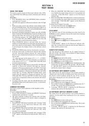
seconds. Use this mode when returning the set to the customer after repair. Select CD function and without dics inserted. 3. SECTION 3 TEST MODE
HCD-SH2000
PANEL TEST MODE This mode is used to check operations of the Amplifier section. If you...
Service Manual - Page 12
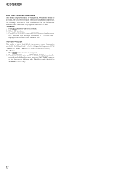
... 1-AM10 are set to be displayed on the fluorescent indicator tube. Procedure: 1. Press @/1 button to TUNER automatically.
12 This mode only applied when there is changed to turn on the system. 2. The message "LOCKED" or "UNLOCKED" displayed on the fluorescent indicator tube. The function is disc. HCD-SH2000
DISC THEFT PREVENTION...
Service Manual - Page 13
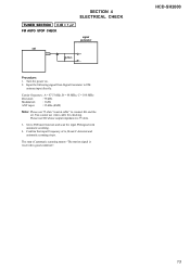
... 0 dB = 1 ȝV FM AUTO STOP CHECK
SECTION 4 ELECTRICAL CHECK
signal generator
set .
Turn the power on. 2. Set to connect SG and the set
+ 75
- Carrier frequency : A = 87.5 MHz, B = 98 MHz, C...input directly. You cannot use SG whose output impedance is received in good condition".
HCD-SH2000
13 Confirm that input Frequency of automatic scanning means "The station signal ...
Service Manual - Page 14
HCD-SH2000
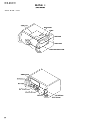
• Circuit Boards Location
SECTION 5 DIAGRAMS
DAMP board
MS-214 board TUNER MAIN board
DMB21 board SWITCHING REGULATOR
DISPLAY board BUTTON board
MIC board
BUTTON LED board VOLUME LED board USB board
VOLUME board AUDIO-IN board
14
Service Manual - Page 19

.... Note: The components identified by mark 0 or dotted line with a VOM (Input impedance 10 MΩ). Parts face side: Parts on Schematic Diagram: • All capacitors are in E model E51 : Chilean and Peruvian models EA : Saudi Arabia model MX : Mexican model MY : Malaysia model SAF : South African model
HCD-SH2000
19
19
HCD-SH2000
Ver. 1.1 t Indication...
Service Manual - Page 20

... (Page 47)
VOLUME
A BOARD CN1000 (Page 45)
AUDIO-IN
H BOARD NO1200 (Page 51)
11 (11)
CN704
CN705
(CHASSIS)
G
DAMP BOARD CN1400 (Page 37)
B
DAMP BOARD CN1401 (Page 37)
J
HCD-SH2000
20
20
Note: Refer to distinguish SUFFIX-11 and SUFFIX-12. F
-&%
41&",&3
3
G
H
I
F700
3
1
3
1
J500
MAIN BOARD
(Component side)
DMB21
I BOARD CN4604 (Page 32)
DMB21...
Service Manual - Page 22

... CN1000 (Page 45)
AUDIO-IN
H BOARD NO1200 (Page 51)
12 (12)
(CHASSIS)
G
DAMP BOARD CN1400 (Page 37)
B
DAMP BOARD CN1401 (Page 37)
J
HCD-SH2000
Note 1: Refer to the servicing notes "MAIN BOARD DISCRIMINATION" (page 5) for Circuit Boards Location. • : Uses unleaded solder.
1
2
3
4
5
6
7
8
9
10
11
12
13
14
15
A
MAIN BOARD (Component side)
B
TUNER
J BOARD...
Service Manual - Page 32

When this part on the DMB21 board cannot exchange with single.
DMB21 BOARD (Component Side) - • See page 14 for Circuit Boards Location. • : Uses unleaded solder.
1
2
3
4
5
6
7
8
9
10
11
12
13
14
15
A B C D E F G H I
J
HCD-SH2000
DMB21 BOARD (Component side) NC
(CHASSIS)
MAIN
I BOARD
CN702 (Page 20) (Suffix 11) (Page 22) (Suffix 12)
MAIN
F BOARD
CN701 (Page...
Service Manual - Page 63

... at "L" in this set
I Laser power monitor ...setting terminal Not used
I Reset signal input from the system controller "L": reset
I IR control signal input terminal Not used
I/O Two-way audio serial data with the USB controller
- Power supply terminal (+3.3V)
63 Power supply terminal (+3.3V)
- Power supply terminal (+3.3V)
I/O Two-way data bus with the SD-RAM
- HCD-SH2000...
Service Manual - Page 64

... terminal
- Power supply terminal (+3.3V)
O Component video (Y) signal output terminal Not used O Component video (Pb/Cb) signal output terminal Not used O Component video (Pr/Cr) signal output terminal Not ... Ground terminal I Audio data input from the coil/motor driver
- Power supply terminal (+3.3V) I Full scale adjustment terminal
- Power supply terminal (+3.3V)
- HCD-SH2000
Pin No. 69...
Service Manual - Page 65
...Chilean and Peruvian models EA : Saudi Arabia model MX : Mexican model MY : Malaysia model SAF : South African model
6-1. MAIN SECTION
#1
10
HCD-SH2000
Ver. 1.1
The components identified by mark 0 or dotted line with part number specified.
7
1 8
#2
4 4 6
4
not supplied
back panel section
11
#1
not supplied
9
3
#1
54
6
4
4
chassis section
3
1
front panel section...
Service Manual - Page 66
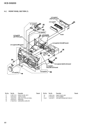
..., COMPLETE
Remark
Ref. HCD-SH2000
6-2. No.
56 57 FL901
Part No.
FRONT PANEL SECTION... (1)
not supplied (DISPLAY board)
not supplied
52
not supplied
52
not supplied (BUTTON board)
55
not supplied
52
not supplied (Button board)
FL901
not supplied (MIC board)
54 52
57
not supplied
51
not supplied (VOLUME board)
52 52
53 52
not supplied (AUDIO...
Service Manual - Page 70

... SWITCH, TACTILE (TUNING - HCD-SH2000
Ver. 1.1 AUDIO-IN BUTTON
BUTTON LED
SECTION 7 ELECTRICAL PARTS LIST
Note: • Due to standardization, replacements in
the parts list may have some difference ...components used on the set. • -XX and -X mean standardized parts, so they are critical for routine service. Part No.
When indicating parts by mark 0 or dotted line with part...
Service Manual - Page 82

...No. No. Description
IC805 8-759-909-71 IC BA4558F
Remark
< JACK >
J500 1-794-981-11 JACK, PIN 4P (GAME AUDIO IN R/L, DVD/SAT AUDIO IN R/L)
< COIL >
L751 1-414-406-11 INDUCTOR L803 1-481-903-11 INDUCTOR L804 1-481-903-11 INDUCTOR L805 1-... 1/16W 5% 1/16W
R129 1-218-965-11 METAL CHIP 10K R130 1-218-965-11 METAL CHIP 10K
5% 1/16W 5% 1/16W
82
Ref. Part No. HCD-SH2000
Ver. 1.1
MAIN
Ref.
Similar Questions

Speaker Wire Connector
looking for part number: 1-839-129-11 and 1-839-128-2
looking for part number: 1-839-129-11 and 1-839-128-2
(Posted by Crsj1981 2 years ago)

Parts Of Sony Hcd Sh2000
Dear Sir.I would like to ask you regarding Sony HCD-SH2000 electronic parts number Main Board. Damp...
Dear Sir.I would like to ask you regarding Sony HCD-SH2000 electronic parts number Main Board. Damp...
(Posted by rizwanbutt94 6 years ago)

Sony Str De715 Display Trouble
I have a SONY str de715 and the display does not work. I'vetried to increase the brightness and repl...
I have a SONY str de715 and the display does not work. I'vetried to increase the brightness and repl...
(Posted by Anonymous-160051 7 years ago)
Where Can I Purchase An Amp Board For My Set, And Whats The Cost
(Posted by preddierandy 9 years ago)

Purchase Parts
where can I secure a communication /loading belt for myHTC-NX1/NX3AV. Sony Mini HI-FI component syst...
where can I secure a communication /loading belt for myHTC-NX1/NX3AV. Sony Mini HI-FI component syst...
(Posted by tonygtorres9923 9 years ago)