Sony HCD-SH2000 Support Question
Sony HCD-SH2000 Support Question
Find answers below for this question about Sony HCD-SH2000.Need a Sony HCD-SH2000 manual? We have 1 online manual for this item!
Question posted by preddierandy on April 6th, 2015
Where Can I Purchase An Amp Board For My Set, And Whats The Cost
The person who posted this question about this Sony product did not include a detailed explanation. Please use the "Request More Information" button to the right if more details would help you to answer this question.
Current Answers
Answer #1: Posted by TechSupport101 on April 6th, 2015 5:29 AM
TechSupport101

Member since:
May 24th, 2013 Points: 12,171,305

Member since:
May 24th, 2013 Points: 12,171,305
You can do so by using the official Sony parts portal here http://esupport.sony.com/US/p/model-accessories.pl
Related Sony HCD-SH2000 Manual Pages
Service Manual - Page 1
...
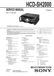
E Model
Ver. 1.1 2011.09
• HCD-SH2000 is the tuner, USB, CD and amplifier section in FST-SH2000/LBT-SH2000.
• "WALKMAN" and "WALKMAN" logo are registered trademarks of Sony Corporation. • MPEG Layer-3 audio coding technology and patents licensed from Fraunhofer IIS and
Thomson. • Windows Media is either a registered trademark or...
Service Manual - Page 2
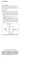
...be measured by means of a VOM or battery-operated AC voltmeter. REPLACE THESE COMPONENTS WITH SONY PARTS WHOSE PART NUMBERS APPEAR AS SHOWN IN THIS MANUAL OR IN...must not exceed 0.5 mA (500 microamperes). HCD-SH2000
SAFETY CHECK-OUT After correcting the original service problem, perform the following safety check before releasing the set to the customer: Check the antenna terminals, ...
Service Manual - Page 3
... 5-21. AUDIO-IN Board 51 5-37. Chassis Section 68 6-5. TEST MODE 11
4. MAIN Board (2/4) (Suffix 12) - .. 29 5-15. EXPLODED VIEWS 6-1. Main Section 65 6-2. Schematic Diagram - ELECTRICAL PARTS LIST 70
3 MAIN Board (3/4) (Suffix 12) - .. 30 5-16. VOLUME Board 45 5-31. VOLUME LED, BOTTON LED AND TUNER Board 50
5-36. Schematic Diagram - HCD-SH2000
TABLE OF...
Service Manual - Page 4
... The flexible board is easily damaged and should be set to ordinary solder.
... a disc control area called the Lead-in MPEG 1 Audio Layer 3 format.
2) A logical format of fi...BOARD When the MS-214 board is defective, exchange the entire MD (AU) ASSY.
4 HCD-SH2000
Ver. 1.1
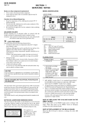
SECTION 1 SERVICING NOTES
Notes on chip component replacement • Never reuse a disconnected chip component...
Service Manual - Page 5
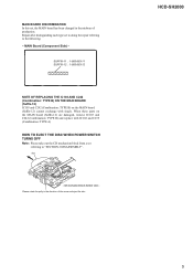
... TURNS OFF Note: Please take out the CD mechanism block from a set to doing the repair referring to "SECTION 2 DISASSEMBLY". HCD-SH2000
5 Repair after distinguishing each type set
referring to the following. - CD mechanism block bottom view - MAIN BOARD DISCRIMINATION In this set, the MAIN board has been changed in the direction of production.
disc
- SUFFIX-11...
Service Manual - Page 6
HCD-SH2000
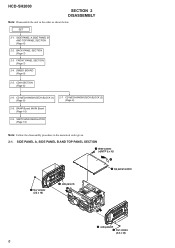
SECTION 2 DISASSEMBLY
Note: Disassemble the unit in the numerical order given. 2-1.
BACK PANEL SECTION (Page 7)
2-3. DMB21 BOARD (Page 8)
2-5. CD MECHANISM DECK BLOCK (2) (Page 9)
2-8. SET
2-1. SWITCHING REGULATOR (Page 10)
Note: Follow the disassembly procedure in the order as shown below. CD MECHANISM DECK BLOCK (1) (Page 9)
2-7. SIDE PANEL A, SIDE PANEL B AND ...
Service Manual - Page 11
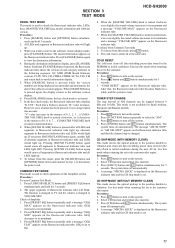
... again, another half of 0, 9, 8, 7 ... Press [ISOLATOR] button, the key check mode is set to check operations of AM channels can be toggled between 9 kHz and 10 kHz. The upper segments of...1. SECTION 3 TEST MODE
HCD-SH2000
PANEL TEST MODE This mode is used to the customer after all data including preset data stored in the following sequence: SC, MTK (DMB Board firmware version), UI...
Service Manual - Page 19

... area in E model E51 : Chilean and Peruvian models EA : Saudi Arabia model MX : Mexican model MY : Malaysia model SAF : South African model
HCD-SH2000
19
19
HCD-SH2000
Ver. 1.1
Note: The components identified by mark 0 or dotted line with respect to normal production tolerances. • Waveforms are taken with a oscilloscope. Replace only with...
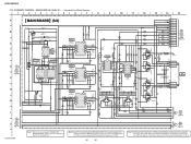
Service Manual - Page 20

... (Page 47)
VOLUME
A BOARD CN1000 (Page 45)
AUDIO-IN
H BOARD NO1200 (Page 51)
11 (11)
CN704
CN705
(CHASSIS)
G
DAMP BOARD CN1400 (Page 37)
B
DAMP BOARD CN1401 (Page 37)
J
HCD-SH2000
20
20
Note: Refer to distinguish SUFFIX-11 and SUFFIX-12.
F
-&%
41&",&3
3
G
H
I
F700
3
1
3
1
J500
MAIN BOARD
(Component side)
DMB21
I BOARD CN4604 (Page 32)
DMB21
F BOARD CN602 (Page 32...
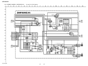
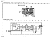
Service Manual - Page 22

... CN1000 (Page 45)
AUDIO-IN
H BOARD NO1200 (Page 51)
12 (12)
(CHASSIS)
G
DAMP BOARD CN1400 (Page 37)
B
DAMP BOARD CN1401 (Page 37)
J
HCD-SH2000
Note 1: Refer to the servicing notes "MAIN BOARD DISCRIMINATION" (page 5) for Circuit Boards Location. • : Uses unleaded solder.
1
2
3
4
5
6
7
8
9
10
11
12
13
14
15
A
MAIN BOARD (Component side)
B
TUNER
J BOARD
CN1601 (Page 49...
Service Manual - Page 30
... 50V C809
23
24
25
MAIN
6 26
BOARD
(4/4)
27
(Page 31)
28
29
30
MAIN
7 BOARD
31
(4/4)
32
(Page 31)
HCD-SH2000
Note 1: Refer to the servicing notes "MAIN BOARD DISCRIMINATION" (page 5) for IC Block Diagrams....4.7k
C885
C884
10
10
16V
16V
IC600
OP-AMP
IC600
BA4558F
4.5
9
1 OUTPUT VCC 8
4.5
4.5
2 INPUT- MAIN board (Suffix-12) that has not been changed appears...
Service Manual - Page 42
...13
14
15
R1618
/AMP-RESET
/AMP-OTW /AMP-SD
5.2 -5.1 -5.2...BOARD (2/4) (Page 40)
13
14 15
31 R1607 100k
R1608 100k
DAMP
18 32
BOARD
29
(3/4)
34
(Page 41)
35
33
30
28
CN1405 3P
JL1486
1
JL1487
2
FAN+ FAN-
3 FAN+
M891 DC FAN
DAMP FAN
C1656 0.1 C1655 0.1 C1643 0.1 C1580 0.1
CN1404 3P
3
JL1484
2
JL1483
1
FAN+ FANFAN+
M891 DC FAN
SMPS FAN
HCD-SH2000
42
42 HCD-SH2000...
Service Manual - Page 43
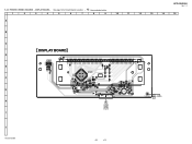
HCD-SH2000
Ver. 1.1
5-28. DISPLAY BOARD - • See page 14 for Circuit Boards Location. • : Uses unleaded solder.
1
2
3
4
5
6
7
8
9
10
11
12
13
14
15
A
B
C
DISPLAY BOARD
D
C902
JL902
IC982
55
50
27
21
6
1
FL901
C952
JL957
JR JR909JL931
JL932 JL933 JL934 JL935 JL936 JL937 JL939 JL941 JL943 JL945 JL947 JL949 JL951 ...
Service Manual - Page 45
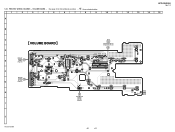
PRINTED WIRING BOARDS - HCD-SH2000
Ver. 1.1
5-30. VOLUME BOARD - • See page 14 for Circuit Boards Location. • : Uses unleaded solder.
1
2
3
4
5
6
7
8
9
10
11
12
13
14
15
A
B
R1026
C
VOLUME BOARD
MAIN BOARD CN105 (Page 20) (Suffix 11) (Page 22) (Suffix 12)
S1013
A
EJECT
D
JL1008 JL1010 JL1012 JL1014 JL1017 JL1020
JL1079 JR JR1040
JL1064
JL1097
JL1003 ...
Service Manual - Page 52
...
13
C1323
1-883-867- (13)
E
5-39. MIC BOARD -
1
2
3
4
5
6
7
8
9
10
11
12
13
A
MIC BOARD
IC1300
MIC AMP
B C
D1300 DA2J10100L CN1300 4P
C1301 0.1 50V
R1300 1M
R1301...
JL1301 JL1302
C1309 0.1
C1311 220 10V
R1311 10k
D
BOARD NO1250
MIC GND 2 A+9V 1
JL1303
C1322 C1323
(Page 48)
D1302
0.1 1000p
MC2840-T112-1
14
MIC IN
E
HCD-SH2000
52
52
15 15 SCHEMATIC DIAGRAM...
Service Manual - Page 57

...
DECIMATION FILTERS
AUDIO INPUT PORT
RATE ESTIMATOR
AUDIO OUTPUT
PORT
BYPAS 9 IFMT0 10 IFMT1 11 IFMT2 12
RST 13 MUTE 14
CONTROL LOGIC
28 MODE2 27 MODE1 26 MODE0
25 BCKO 24 LRCKO 23 SDOUT
22 VDD 21 DGND
20 TDMI
19 OFMT0 18 OFMT1 17 OWL0 16 OWL1 15 RDY
HCD-SH2000
57
Service Manual - Page 61

...to Digital Amp
27
/HUB...board
44
HUB-RESET
O MTK Hub Board reset pin
45
HUB-VBUS-DETECT O Hub Power (V-DET) Control Port
46
FLASH-MEMORY
O Update software recovery
47
AUDIO-DATA
O Serial data output to audio signal processor, R2A15216FP
48
NO-USE
O Unused
49
AUDIO... Ground terminal
CNVSS
- HCD-SH2000
• IC Pin Function Descriptions MAIN BOARD (1/4) IC100 R5F3650KBDFA (SYSTEM ...
Service Manual - Page 62
...Board power monitor input pin (A/D input) Unused Key input terminal (A/D input) USB B RED LED Control Pin. USBB-LED-BLUE
O
Description Speaker Left RED LED Control Pin. "H": LED on
62 "H": Mic detected Unused USB A LED Control Pin. PCONT-MAIN
O
VSS
- "H": 13V Fan Control Switch "H": fan on Amplifier Pin. HCD-SH2000... Unused Digital Amp Reset Pin Digital Amp Shutdown Protection ...
Service Manual - Page 63

...output to the system controller
O Serial data output to the system controller
I ICE mode enable setting terminal Not used
I Reset signal input from the optical pick-up block
- HCD-SH2000
DMB21 BOARD (2/3) IC101 CXD9968R (LE)
Pin No. 1 2 3 4 5 6 7 8 9 10...4V) output terminal
I Current reference input terminal Fixed at "L" in this set
I /O Two-way audio serial data with the SD-RAM
-
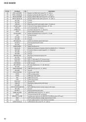
Service Manual - Page 70

...HCD-SH2000
Ver. 1.1 AUDIO-IN BUTTON
BUTTON LED
SECTION 7 ELECTRICAL PARTS LIST
Note: • Due to standardization, replacements in
the parts list may have some difference from the parts specified in the diagrams or the components used on the set...
5% 1/10W
R1207 1-216-838-11 METAL CHIP 27K
5% 1/10W
BUTTON BOARD
< DIODE >
D1251 D1256 D1257 D1258 D1259
6-502-469-01 6-503-224...
Similar Questions

Where Can I Purchase The System Control Cord For A Sony Hcd-541? How Much Is It
(Posted by bbrwnydgrl 8 months ago)


Speaker Wire Connector
looking for part number: 1-839-129-11 and 1-839-128-2
looking for part number: 1-839-129-11 and 1-839-128-2
(Posted by Crsj1981 2 years ago)

No Sound When Using Hdmi Cable To My Tv
i am not getting any sound through my amp when plugging an HDMI cable from my tv to the amp all othe...
i am not getting any sound through my amp when plugging an HDMI cable from my tv to the amp all othe...
(Posted by andreagiglio1970 3 years ago)
