
Sharp XL-HP737 Support Question
Sharp XL-HP737 Support Question
Find answers below for this question about Sharp XL-HP737.Need a Sharp XL-HP737 manual? We have 1 online manual for this item!
Question posted by Anonymous-150115 on March 23rd, 2015
Anyone Know Why Only 2 Of The 5 Cd Slots Would Work?
This is a Sharp 5 CD shelf system and only two of the cd slots read and play the music. Any ideas as to how to fix this?
Current Answers

Related Sharp XL-HP737 Manual Pages
Service Manual - Page 1
...[1] BLOCK DIAGRAM 4-1
CHAPTER 5. FLOWCHART [1] TROUBLESHOOTING 7-1
CHAPTER 8. XL-HP737
SERVICE MANUAL
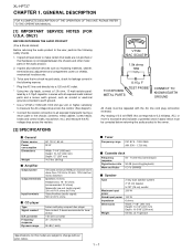
No. GENERAL DESCRIPTION [1] IMPORTANT SERVICE NOTES (FOR
U.S.A....PARTS 1-2
CHAPTER 2.
CONTENTS
CHAPTER 1.
S3410XLHP737U
MICRO COMPONENT SYSTEM
MODEL XL-HP737
XL-HP737 Micro Component System consisting of XLHP737 (main unit) and CP-HP737 (speaker system).
• In the interests of...
Service Manual - Page 2
XL-HP737
AXSMECeLuaHrdH-vrHkiAioPcePe7tP73M3T77aEnuRal1. ONLY)
BEFORE RETURNING THE AUDIO PRODUCT
(Fire & Shock Hazard)
Before returning the audio product to the user, perform the following manner.
* Plug the AC line cord directly into 6 ohms from 100 Hz to 20 kHz, 10% total harmonic ...
Service Manual - Page 3
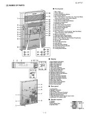
... (Audio Signal) Input Jacks 8. Subwoofer Pre-output Jack
I Rear panel
1. Power On/Stand-by Button 4. Headphone Jack 10. Illumination Light 14. Disc Track Up or Fast Forward, Tape Fast Wind,
Tuner Preset Up, Time Up Button 16. MP3 Total Indicator 5. Disc Repeat Play Indicator 19. [3] NAMES OF PARTS
1
2 3 4 5 6 7 8
9
21
23
22
24
XL-HP737...
Service Manual - Page 4
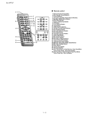
CD Button 9. Tuner (Band) Button 10. Video/Auxiliary Button 12. Memory/Set Button 19. Disc Play or Repeat Button 21. Extra Bass Button 7. Disc Clear/Dimmer Button 15. Tape Reverse Play...
1 - 3 Tape Forward Play Button 22. Disc Track Down or Fast Reverse, Tape Fast Wind,
Tuner Preset Down, Time Down Button 29. Tape Stop Button 18. Clock/Timer Button 27. XL-HP737
1
2 3
4 5 ...
Service Manual - Page 5
...)
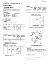
TAPE MECHANISM
Tape Motor
Variable Resistor in motor. CD SECTION
• Adjustment
Since this CD system incorporates the following automatic adjustment functions, readjustment is...Play: TW-2111
Specified Value Over 80 g
• Torque Check
Torque Meter Play: TW-2111 Fast forward: TW-2231 Rewind: TW-2231
Specified Value 30 to 80 g.cm 70 to 180 g.cm 70 to 180 g.cm
2. ADJUSTMENTS
XL-HP737...
Service Manual - Page 6

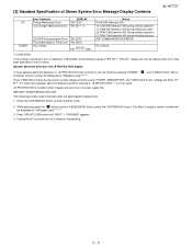
...CD function, DSP cannot read initial data.
* 'CHECKING'
If Error is detected, 'CHECKING' will be displayed instead of 'ERCD**'. 'ER-CD**' display will be displayed when error had been detected for 10 secs. CD... initialize process. TRAY error. Can't detect TRAY switch when TRAY is moving . XL-HP737
2) Tracking balance adjustment 3) Gain adjustment (The gain is compensated inside the IC ...
Service Manual - Page 7
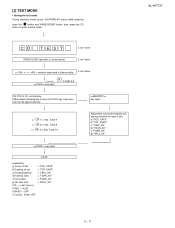
...CD
button to page 2-4
key input. CD T EST
OPEN/CLOSE operation is input into PLAY key, track number can be appoint directly. IL isn't done IL isn't done
>,>buttons make pick's slide possible. Do normal play..."FOF_XXXX" b) "TOF_XXXX" c) "TBAL_XX" d) "TGAN_XX" f) "FGAN_XX" g) "RFLS_XX"
--------
XL-HP737
2 - 3
FLAT
X-BASS - [2] TEST MODE
• Setting the test mode During stand...
Service Manual - Page 9
... is ready for the 5 th times.
PLL Unlock.
(*) CHECKING:
If CD changer mechanism error is condition when irregular process occur on power supply line.
... of Stereo System Error Message Display Contents
XL-HP737
CD TUNER
Error Contents
DISPLAY
Pickup Mechanism Error.
'ER-CD01'
CD Changer Mechanism Error. 'ER-CD**' (*)
CD DSP Communication Error. BEFORE TRANSPORTING THE UNIT...
Service Manual - Page 11
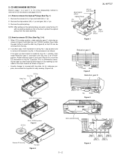
... the stop washer (A3) x 1 pc and gear (A4) x 1 pc. 3. When CD is at play position and to remove CD located in tray No. 3, the procedure is as shown in Figure 2 until Disc tray is at...clock-wise (Figure 3) to move the CD mechanism to remove CD Disc (See Fig. 2~6)
1.
Stop Washer (A3) x1
Optical Pickup
CD Mechanism
(A1) x2 ø2.6 x5mm
XL-HP737
Shaft Gear (A2) x1 (A4) x1...
Service Manual - Page 12

... PWB CD MP3 PWB (Note 1)
CD Mechanism
PROCEDURE 1. Screw K2) x 8 3. Screw A1) x11 1. Hook C1) x2 2. Screw F1) x1 2.
Socket F2) x1 1. Screw G1) x2 2. Screw L1) x 4 1. Screw P1) x4 2. XL-HP737
[2] ...ø3x10mm
(A1) x2 ø3x8mm
(A1) x2 ø3x8mm
Rear Panel Bottom
Figure 1
CD Changer Unit
CD MP3 PWB (C3) x1
(C2) x1 Front Panel
Rear Panel Bottom
(D1) x9 ø3x8mm...
Service Manual - Page 14

REC/PLAY Q107 Q108 MUTING
ñ20dB ATT Q601
Q602
Q603 Q604
+B5 A_+... L 10
R 15
TUNER L 11
R 14
CD L 12
R 13
DI 1
CE 2
IC601 CLK 24
LC75341
21 R
AUDIO PROCESSOR 4 L
13
+B5
P.B 4 L PB
21 R
7 18 8 17 3 23 +B5
H/N 7 L REC 18 R
IC101 AN7345K PLAYBACK AND RECORD /PLAYBACK AMP. XL-HP737
AXSMECeLuaHrdH-vrHkiAioPcePe7tP73M3T77aEnuRal4. DIAGRAMS
[1] BLOCK DIAGRAM
FM ANTENNA TERMINAL...
Service Manual - Page 15
...B10
KEY SW701-SW705 SW709-SW728
VOLUME VR701
+B9(SW_+5V)
+B_PROTECT
Q703 +B10 RESET
VDD -20dBATT T_BIAS T_REC/PLAY VDD CLK DI DO CE
LED707 Q710
1 2 3 4 6 7 11 12 15 16 21
SP DET +...Q905
SP_RLY 47 24 17 18 19 20
+B4(8V) +B7(A_5V) +B8(D_5V)
TO CD SECTION
DRIVER
FAN MOTOR M971
Q906
M
+B7(A_5V)
RL914 RELAY
+B3
SO901 SPEAKER TERMINAL
JK701 ... 4-2 BLOCK DIAGRAM (2/4)
4 - 2 XL-HP737
.
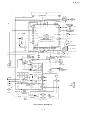
Service Manual - Page 16

...SW2
SW3 TRAY SW2
PICKUP UNIT
FOCUS COIL TRACKING COIL
Q1
LASER DRIVER
Q2 +3.3V
SW1A PICKUP-IN
Figure 4-3 BLOCK DIAGRAM (3/4)
4 - 3
XL-HP737
TO MAIN SECTION
TO DISPLAY SECTION
CNP2 1 2 3 4 5 6 7 8
CNP5 16 15 14 13 12 11 10 9 8 7 ...MO_B+/CONT3 36
M0_SPEED/CONT6 70
IC1
MOT_A+/CONT5 74
LC78648E MOT_A-/CONT4 75
CD DIGITAL SIGNAL FDO 21
PROCESSOR
TDO 22
SLDO 23
SPDO 24
PU-IN/CONT1...
Service Manual - Page 18

XL-HP737
AXSMECeLuaHrdH-vrHkiAioPcePe7tP73M3T77aEnuRal5. CIRCUIT DESCRIPTION
[1] WAVEFORMS OF CD CIRCUIT
1 IC1 21
Stopped CH1=500 mV DC 10:1
T
FDO
1
CH3=500 mV DC 10:1
500 ms/div (500 ms/div) NORM:20 kS/s
2 IC1 ...
Service Manual - Page 21

...the capacitor without any symbol is microfarad.
CIRCUIT SCHEMATICS AND PARTS LAYOUT
[1] NOTES ON SCHEMATIC DIAGRAM
XL-HP737
• Resistor:
To differentiate the units of resistors, such symbol as K and M are...kohm and the resistor without such a symbol is ohm-type resistor. In the CD section, the CD is being played back. 3. In the tuner section, indicates AM indicates FM stereo
2. NO...
Service Manual - Page 22

... DIAGRAM can be found on page 6-1
1
2
3
4
5
6
Figure 6-2 SCHEMATIC DIAGRAM (1/10) 6 - 2 XL-HP737
[3] WIRING SIDE OF P.W.BOARD/SCHEMATIC DIAGRAM
MAIN PWB-A1(1/2)
FM SIGNAL
R601 1K
CD SIGNAL
R602 1K
A
AUX SIGNAL
IC601
C652 220P C651 220P
PLAYBACK SIGNAL
LC75341
C653
RECORD SIGNAL
AUDIO PROCESSOR 220P
1 DI
CLK 24
R605 C609
2 CE
VDD 23
-+
-+ -+
-+
R613...
Service Manual - Page 42

...CD lens cleaner should be used on car CD players or on the laser pickup lens. The CD cleaner disc must not be effective for about 20 seconds and the CD player will hear music...touch the lens with the DSP).
2.2. XL-HP737
AXSMECeLuaHrdH-vrHkiAioPcePe7tP73M3T77aEnuRal7. When the CD does not function
The CD section may be played
2.1. If the CD cleaner brushes become worn out earlier then ...
Service Manual - Page 51

... Memory interface
Function CD left /right clock output. CD subcode data serial input CD subcode block sync signal input. Audio data output. Audio left /right clock... DRAM data bus 6 DRAM data bus 7 Digital I /O system power supply. CD C2 error flag input. IC3 VHiLC78683E-1: MP3 Decoder (LC78683E) (1/2)
XL-HP737
Pin No. 1 2 3 4 5 6
Terminal Name LRSY ADDATA ADBCK ADLRCK C2FIN...
Service Manual - Page 53

...25 26 27 28 29 30 31 32 33 34 35 36 37 38 39 40
XL-HP737
DVDD2 VSS
MDATA0 MDATA1 MDATA2 MDATA3 MDATA4 MDATA5 MDATA6 MDATA7
DVDD3 VSS
MDATA8 MDATA9 MDATA10 ...C2FIN
SFSY PW
SBSY SBCK
RESB
System clockgenerator VCO
+ PLL
DRAM-I/F
CD-DA shockproof (Compressed or uncompressed)
CDROM decoder
CPU-I/F
Data-I/F
MP3 decoder
M U X
Audio I/F
Figure 3 BLOCK DIAGRAM OF IC
STREQ STCK STDAT CRCF FSYNC
ADLRCK ...
Service Manual - Page 55

... band filter comprising capacitor and resistor connection pin and bass/treble output pin. IC601 VHiLC75341/-1: Audio Processor (LC75341)
XL-HP737
Pin No. 13-16 17 18 19 20 21
22
23 24
Terminal Name R1-4 RSEL0... LSEL0 LIN LTRE LBASS LOUT
87
6
54
L4 9 AUX L3 10 DECK L2 11 TUNER L1 12 CD
R1 13 R2 14 R3 15 R4 16
CONTROL CIRCUIT
CONTROL CIRCUIT
CONTROL CIRCUIT
LVref
CCB INTERFACE
RVref
3 VSS...
Similar Questions

Cd 'can't Read' Message
My CD player reads "can't read" when I insert a cd and/or a cd cleaner. This happens with all 5 slot...
My CD player reads "can't read" when I insert a cd and/or a cd cleaner. This happens with all 5 slot...
(Posted by wieve1 5 months ago)

How Do I Get Cd Player To Play Same Disc Again Instead Of Going To Next In Line
my cd play er goes to next disc after completing current disc. used to play same disc over and over ...
my cd play er goes to next disc after completing current disc. used to play same disc over and over ...
(Posted by Anonymous-153079 8 years ago)


I Cant Get The Cd Player To Play. Keeps Asking For A Disc When There Is One In
(Posted by judylindow 11 years ago)

Cd Player Reads 'no Disc'
My brand new DH950P works great in all other modes, but I can't play any CDs. I insert a disk and ge...
My brand new DH950P works great in all other modes, but I can't play any CDs. I insert a disk and ge...
(Posted by georgevan 12 years ago)