
Sharp XL-DK225 Support Question
Sharp XL-DK225 Support Question
Find answers below for this question about Sharp XL-DK225.Need a Sharp XL-DK225 manual? We have 1 online manual for this item!
Question posted by defleming on November 2nd, 2019
How To Cancel Timer
stimersharp stereo how to cancel timer XL dk225
Current Answers
Answer #1: Posted by hzplj9 on November 2nd, 2019 9:12 AM
hzplj9

Member since:
June 25th, 2012 Points: 4,875,710

Member since:
June 25th, 2012 Points: 4,875,710
This is a link to a similar model as yours. The 227 is virtually the same as a 225. Refer to page 30 of the guide to understand the setting of the timer in regard to the clock. It can be frustrating sometimes to get round the settings, and one needs to follow the instructions step by step, and you should see a resolution of your dilemma. A service manual for the 225 is available from the same site.
https://www.manualslib.com/download/489115/Sharp-Xl-Dk227nh.html
Hope that helps.
Related Sharp XL-DK225 Manual Pages
Service Manual - Page 1
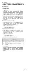
...ADJUSTMENTS [1] CD Section 2-1 [2] Test Mode 2-2 [3] Standard Specification Of Stereo System
Error Message Display Contents 2-4
CHAPTER 3. MECHANICAL DESCRIPTION [1] Removing ...change without notice. XL-DK225
SERVICE MANUAL
No. S7734XLDK225/
MICRO COMPONENT SYSTEM
VIDEO /AUX
MODEL XL-DK225
XL-DK225 Micro Component System consisting of XL-DK225 (main unit) and CP-DK225 (speaker system)....
Service Manual - Page 2
... a different type of the soldering bit, it has poor solder wettability, you are not familiar with the lead-free solder, apply lead-free wire solder.
XL-DK225
AXSMEPeRuLardEr-vMkMiiCocePAePt1U1M55T00aIOnuNaSl FOR USING LEAD-FREE SOLDER
1. The LF symbol indicates lead-free solder, and is attached on and off or the maximum heat-resistance...
Service Manual - Page 3
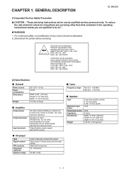
...safety, no modification of electric shock do not perform any circuit should be attempted. 2. GENERAL DESCRIPTION
XL-DK225
[1] Important Service Safety Precaution
CAUTION : "These servicing instructions are qualified to 20 kHz, 10%...- 50 ohms (recommended: 32 ohms) Subwoofer pre-out (audio signal): 200 mV/10 k ohms at 70 Hz
Video/Auxiliary (audio signal): 500 mV/47 k ohms
CD player
Type Signal...
Service Manual - Page 4
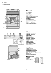
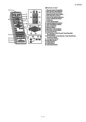
.../WMA Folder Indicator 3. Daily Timer Indicator 10. Disc Play Indicator
Rear panel
3
1. Video Out Jack
8. Video/Auxiliary/iPod Button 11. MP3 Indicator 5. FM Stereo Receiving Indicator 12. FM 75 Ohms Antenna Jack
4
4. Bass Reflex Duct
1
3
4. AC Power Cord
3. Volume Control 13. Extra Bass Indicator 14. AM Loop Antenna Terminal
6. XL-DK225 [3] Names Of Parts...
Service Manual - Page 5
...3. Equalizer Mode Select Button
8
12
5. Disc Play or Pause Button
15. Tuning Down Button
5
20. Clock/Timer Button
1 - 35 Disc Stop Button
13. Tuning Up Button
18 19
17. Video/Auxiliary/iPod Button 11. Power... Display Button
22. iPod Play or Pause Button
16. XL-DK225
Remote control
1
1. Disc Direct Search Buttons
7
4. Tuner (Band) Button
10
10. Folder Button
23.
Service Manual - Page 6
...
3) Gain adjustment (The gain is moving . TRAY error. When it detect cam operation error during initialize process.
* 'CHECKING'
If Error is moving . ADJUSTMENTS
[1] CD Section
1.
XL-DK225
CHAPTER 2.
Can't detect TRAY switch when TRAY is detected, 'CHECKING' will be displayed instead of each disc can be performed under optimum conditions.
Service Manual - Page 7
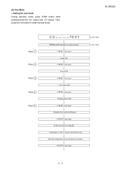
... test mode During stand-by mode, press STOP button while pressing down > key for more than 2 sec. STOP and return to enter the test mode.\
XL-DK225
Step 1 Step 2 Step 3 Step 4 Step 5
CD
TE ST
OPEN/CLOSE operation is using manual. > key input. Focus ON > key input.
key input. Tracking Servo ON...
Service Manual - Page 8
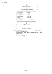
... Offset
= FOFF : XX
f) Tracking Offset
= TOFF : XX
g) RFRP
= RFRP : XX
h) Focus Error
(RW Judgement)
= RW : XX -
XXXX
i) Focus Error
(Other than 1 sec, it directly
To cancel: Power OFF
2 - 3 XL-DK225
STOP and return to Step 1
Note
Sliding the PICKUP with , > button can be set / >> for more than RW Judgement) = DA : XX -
Service Manual - Page 9
...the
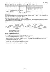
3. [3] Standard Specification Of Stereo System Error Message Display Contents
XL-DK225
CD TUNER
Error Contents
DISPLAY
...CD Changer Mechanism Error. 'ER-CD**' (*)
Focus Not Match/IL Time Over. 'NO DISC'
PLL Unlock. Unplug the AC cord and the unit is detected, 'CHECKING' will be display instead of speaker abnormal
ON
FLASHING
ON
TIMER...
Service Manual - Page 18
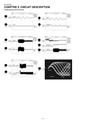
CIRCUIT DESCRIPTION
[1] Waveforms Of CD Circuit
1
FDO
IC1 22
2
TDO
23
IC1
1
FDO
22
IC1
5
SPDO
25
IC1
1
22
FDO
IC1
3
TE
16
IC1
6
28
IC1
PDOUT 0
7
PDOUT 1
27
IC1
1
22
FDO
IC1
3
TE 16
IC1
4
IC1
2 RFOUT
4 2
IC1
RFOUT
5 - 1 XL-DK225
CHAPTER 5.
Service Manual - Page 23
...
TOP VIEW
KDS184
FRONT VIEW
AC AC
10XB60F S4B05GM
FRONT VIEW
FRONT VIEW
343VC3F 503BC2E30
1 23
KIA7805A
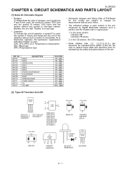
6 - 1 In the tuner section, indicates AM indicates FM stereo
2.
XL-DK225
CHAPTER 6. CIRCUIT SCHEMATICS AND PARTS LAYOUT
[1] Notes On Schematic Diagram
• Resistor: To differentiate the units of resistors, such symbol as K and M are
important for...
Service Manual - Page 32
XL-DK225
A B C D E F G H
1
IPOD CONNECTION
RESISTOR WITH 1% TOLERANCE
2
3
4
5
6
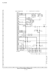
Figure 6-9: iPOD SCHEMATIC DIAGRAM (1/2)
6 - 10
Service Manual - Page 34
XL-DK225
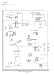
[4] Charts Of Connecting Wires
WH
F F C 7 0 5
TUNER PACK
9
FFC301
A
ANTENNA
1
FM
GND
9
AM
F F C 3 0 1
B
CNS601 9 8 7 6 5 4 3 2 1
1
9
1
TRANSIT iPOD
PWB-A4 1
12
2 4 6 8 10 12 CNPU4 1 3 5 7 9 11
BL
WH
BL
...
Service Manual - Page 35
XL-DK225
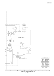
FROM DISPLAY PWB-B1
CNP702
F F C 7 0 5
12
1
F F C 7 0 2
1
10
11 9 7 5 3 1 12 10 8 6 4 2
CNP3
9 8 7 6 5 4 3 2 1
CNP5
2 4 6 8 10 13579
CNP6
1 1
2 4 6 8 10 1 3 5 7 9 11
C N P 4
T O CD CHANGER MECHANISM UNIT
1
FFC4
T O CD MOTOR PWB
1 2 3 4 5 6 ...
Service Manual - Page 36
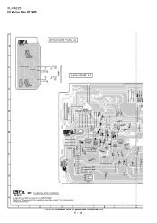
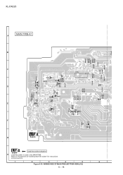
Figure 6-13: WIRING SIDE OF MAIN PWB (TOP VIEW) (1/2)
6 - 14 Refer to "Precautions for handling lead-free solder" for instructions and precautions. XL-DK225
[5] Wiring Side Of PWB
SPEAKER PWB-A3
L-CH L-CH
R-CH R-CH
MAIN PWB-A1
SO901 SPEAKER TERMINAL
123 4
1 3 5 7 9 11 13 15 17 2 4 6 8 10 12 14 ...
Service Manual - Page 37
XL-DK225
TRANSIT iPOD PWB-A4
2 4 6 8 10 12 1 3 5 7 9 11 1 2 3 4 5 6 7 8 9 10 11 12
2 468 1 3 5 79
2 4 6 8 1012 1 3 5 7 9 11
1 2 3 4 5 6 7 8 9 10 11121314 15 5 4 32 1
B CE 12
VIDEO/AUX IN L-CH and R-CH
VIDEO OUT
SUBWOOFER PRE-CUT
Figure 6-14: WIRING SIDE OF MAIN PWB (TOP VIEW) (2/2)
6 - 15
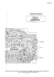
Service Manual - Page 38
XL-DK225 MAIN PWB-A1
Lead-free solder indication Lead-free solder is used in the MAIN PWB. Figure 6-15: WIRING SIDE OF MAIN PWB (BOTTOM VIEW) (1/2)
6 - 16 Refer to "Precautions for handling lead-free solder" for instructions and precautions.
Service Manual - Page 40
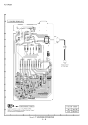
Figure 6-17: WIRING SIDE OF POWER PWB
6 - 18
COLOR TABLE W H WHITE B K BLACK Refer to "Precautions for handling lead-free solder" for instructions and precautions. XL-DK225
POWER PWB-A2
5
4
6
3
7
8
2
9
1
6 54321
T.F.
8 9 10 11 12 13 14 15 16 17
BC E
BK WH
POWER SUPPLY AC 120V~60Hz
BC E
10 9 8 7 6 5 4 3 2 1
1
2
3
6 54 32 1
Lead-...
Service Manual - Page 42
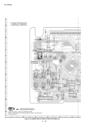
Figure 6-18: WIRING SIDE OF DISPLAY PWB (TOP VIEW) (1/2)
6 - 20 XL-DK225 DISPLAY PWB-B1
51 50 49 48 47 46 45 44 43 42 41 40 39 38 37 36 35 34 33 32 31 30 29 28 2
2 4 6 8 10 12 14 16 1 3 5 7 9 11 13 15 17
9 7531 10 8 6 4 2
Lead-free solder indication Lead-free solder is used in the DISPLAY PWB. Refer to "Precautions for handling lead-free solder" for instructions and precautions.
Service Manual - Page 58
...document has been published to change without notice. " are subject to be used for maintaining the safety of XL-DK225 (main unit) and CP-DK225 (speaker system). XL-DK225
PARTS GUIDE
MICRO COMPONENT SYSTEM
MODEL XL-DK225
XL-DK225 Micro Component System consisting of the set . The contents are important for after sales service only.
CONTENTS
[1] INTEGRATED CIRCUITS [2] TRANSISTORS...
Similar Questions

'standby' Mode
In Standby mode my info screen continuously flashes rapidly through what appears to be power informa...
In Standby mode my info screen continuously flashes rapidly through what appears to be power informa...
(Posted by debench 1 year ago)

Error Code 21.
I have an error code of 21 and no disc plays nor do any open.
I have an error code of 21 and no disc plays nor do any open.
(Posted by tcgaffy 1 year ago)

My Sharp Xl-dk255 Won't Turn On, But Timer Light Is Flashing.
(Posted by nancyrobinson 3 years ago)
System Won't Power Up, Timer Light Flashes.
System does not power up. Timer light flashes.
System does not power up. Timer light flashes.
(Posted by Anonymous-127873 10 years ago)

Our Xl-dh259p Turns Off After 30 Min. I Checked The Timer And It Was Set At 00
Our xl-dh259p turns off after 30 min, I checked the timer and it was set at oo - any tricks to setti...
Our xl-dh259p turns off after 30 min, I checked the timer and it was set at oo - any tricks to setti...
(Posted by darrellwt 11 years ago)