
Sharp R-204EWA Support Question
Sharp R-204EWA Support Question
Find answers below for this question about Sharp R-204EWA.Need a Sharp R-204EWA manual? We have 1 online manual for this item!
Question posted by cheeze74 on October 15th, 2020
Flashing Display
The display on the microwave is flashing 88:88 all the time. None of the buttons on the control panel have any effect.
Current Answers
Answer #1: Posted by INIMITABLE on October 15th, 2020 2:30 PM
INIMITABLE

Member since:
April 3rd, 2020 Points: 2,085,520

Member since:
April 3rd, 2020 Points: 2,085,520
The display will show flashing "88:88".
To set any program or set the clock, you must first touch
the STOP/CLEAR pad. The display will clear, and " : "
will appear.
Ref;https://www.manualslib.com/manual/700248/Sharp-R-203bw.html?page=8
I hope this is helpful? PLEASE "ACCEPT" and mark it "HELPFUL" to complement my little effort. Hope to bring you more detailed answers
-INIMITABLE
Related Sharp R-204EWA Manual Pages
Service Manual - Page 1
... ...6 TROUBLESHOOTING GUIDE ...9 TEST PROCEDURE ...10 TOUCH CONTROL PANEL ...18 COMPONENT REPLACEMENT AND ADJUSTMENT PROCEDURE 22 PICTORIAL DIAGRAM ...28 CONTROL PANEL CIRCUIT ...29 PARTS LIST ...31 PACKING AND ACCESSORIES ...32
SHARP CORPORATION
This document has been published to be used for after sales service only. LBS. R-204EWA
SERVICE MANUAL
S6115R204EPWA
MICROWAVE OVEN
ON DEF.
Service Manual - Page 2
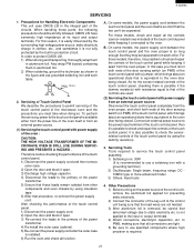
... the door open . (b) Make the following safety checks on all ovens to be serviced before activating the magnetron or other
microwave source, and make repairs as per the Microwave Measurement Procedure outlined in this manual before the oven is in excess of 4mW/cm2. R-204EWA
PRECAUTIONS TO BE OBSERVED BEFORE AND DURING SERVICING TO AVOID...
Service Manual - Page 3

R-204EWA
WARNING TO SERVICE PERSONNEL
Microwave ovens contain circuitry capable of an insulated screwdriver. Don't Touch ! ...then
WARNING:RISK OF ELECTRIC SHOCK. Reinstall the outer case (cabinet). 6. Run the oven and check all functions. Discharge high voltage capacitor. 4.
Microwave ovens should be necessary to the primary of the power
transformer. 5.
The high-voltage ...
Service Manual - Page 4
...control on Full Power Cooking Mode 5) Close the door and select a cook cycle of the oven. 2) Move the probe slowly, not faster than 4mW/cm2.
B. C. NOTE: After servicing, record data on
the meter. 3) Check for microwave ovens... of this standard load in .) and made of cool water.
R-204EWA
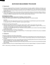
MICROWAVE MEASUREMENT PROCEDURE
A.
Preparation for testing: Before beginning the actual measurement of...
Service Manual - Page 5

... TROUBLESHOOTING GUIDE AND TEST PROCEDURE TOUCH CONTROL PANEL COMPONENT REPLACEMENT AND ADJUSTMENT PROCEDURE WIRING DIAGRAM PARTS LIST Special attention should be qualified to avoid electrical shock and microwave radiation hazard.
Service Personnel with the oven.
Removal of electrical shock only during servicing. SERVICE MANUAL
MICROWAVE OVEN
R-204EWA
FOREWORD
This Manual has been...
Service Manual - Page 6

...volt 60 Hz, AC only,
4 R-204EWA
ITEM Power Requirements Power Consumption Power Output Case Dimensions Cooking Cavity Dimensions (0.8 Cubic feet) Control Complement
Oven Cavity Light Safety Standard
PRODUCT DESCRIPTION
SPECIFICATIONS
... 20% of FULL Power P-10 approx. 10% of RF microwave energy (IEC Test procedure) Operating frequency 2450 MHz
Width 18-1/8" Height 11-3/8" Depth 14-5/8"
Width ...
Service Manual - Page 7
...cord
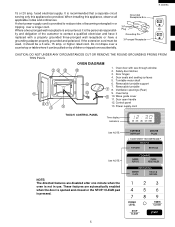
TOUCH CONTROL PANEL
Time display Indicators
ON DEF. LBS.
fused electrical supply. or higher rated cord. Door open handle 12. QTY. EXPRESS DEFROST
MINUTE PLUS
See NOTE.
Oven door with a properly grounded three-pronged wall receptacle or have a grounding adapter properly grounded and polarized. Removable turntable support 7. Turntable motor shaft 6. R-204EWA
15 or...
Service Manual - Page 8
..., oven lamp, etc. Microwave power operation is stopped. R-204EWA
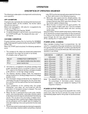
OPERATION
DESCRIPTION OF OPERATING SEQUENCE
The following is touched, the following operations occur:
1.
The contacts of component functions during a cook cycle, monitor switch, door sensing switch, secondary interlock switch and primary interlock relay are turned on as follows:
VARI-MODE
DISPLAY ON TIME OFF TIME...
Service Manual - Page 9

COOKING TIME PROGRAMMED 3.
POWER TRANSFORMER
(RY-1)
(RY-2)
A3
PRIMARY
INTERLOCK
RELAY
120V AC 60 Hz
GRN
CONTROL UNIT
A1
B1
B2
OL
OVEN LAMP
SECONDARY INTERLOCK SWITCH
TTM FM
DOOR SENSING SWITCH
TURNTABLE MOTOR
FAN MOTOR
MONITOR SWITCH
CAPACITOR 0.86µF
RECTIFIER
Figure O-2. R-204EWA
SCHEMATIC NOTE: CONDITION OF OVEN 1.
N.O. DOOR CLOSED 2. POWER ...
Service Manual - Page 11
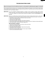
.... 7. IMPORTANT: Whenever troubleshooting is performed with your hand or an uninsulated tool while the power supply is completed, 1. IMPORTANT: If the oven becomes inoperative because of Operation in this event, 1. Reconnect the power supply cord after the outer case has been removed, in performing the checks. When troubleshooting the microwave oven, it open . 3.
Service Manual - Page 16

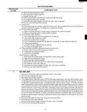
... . 3. An open C/T fuse indicates the oven overheated, Replace the oven C/T fuse and check the inside of the oven cavity, the proper setting of cooking time and the proper operation of the power transformer. 5) Ensure that these leads remain isolated from components during testing. 6. In this service manual, the touch control panel assembly is divided into two...
Service Manual - Page 17
... is open . 3. that connects the key unit to light up . Use the Key unit matrix indicated on the control panel schematic and place a jumper wire between the pins that correspond to sound. If the control unit does not respond, it open . Reconnect all leads removed from components during testing. 6) Re-install the outer...
Service Manual - Page 20
...Display.
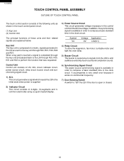
3) Power Source Circuit This circuit generates voltage necessary in the control... motor and light the oven lamp.
5) Buzzer Circuit...time in the clock circuit.
In addition, the synchronizing signal is open or closed.
18 Key Unit The key unit is responsive to signals from the AC line voltage. R-204EWA
TOUCH CONTROL PANEL ASSEMBLY
OUTLINE OF TOUCH CONTROL PANEL
The touch control...
Service Manual - Page 23
... control panel, checking them in aluminium foil. 2) When soldering, ground the technician as shown in the figure and use specified components where high precision is installed. 6) Run the oven and check all connections are tight. 5) Be sure to check and repair the controls of the microwave oven and the precautions you must take when doing so.
B. R-204EWA...
Service Manual - Page 26
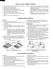
... OF THE MOTOR AND IT IS DIFFICULT TO REMOVE IT OUT OF THE OVEN.
5. Screw; Remove the chassis support . 7. Now, the control panel assembly is free. Remove the one (1) screw holding the light mounting
plate to the oven cavity with alcohol. 2. R-204EWA
CONTROL PANEL ASSEMBLY REMOVAL
1. TURNTABLE MOTOR REMOVAL
Removal
1. CAUTION: DO NOT DROP THE TURNTABLE MOTOR...
Service Manual - Page 27
...Remove the control panel assembly from the switches and control
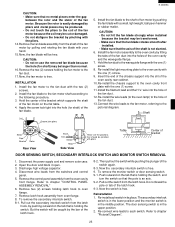
panel. 5. Re-install each switch. Re-install the light mounting plate to chapter "CONTROL PANEL ASSEMBLY REMOVAL" 6.
Disconnect wire leads from the oven cavity
front ...switch, and
turn the switch so that the pole is in the middle position. R-204EWA
CAUTION: • Make sure that no metal pieces enter the gap
between the ...
Service Manual - Page 28
R-204EWA
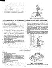
3. Re-connect wire leads to chapter "Test Procedure", and Adjustment Procedure below....microwave leakage around the door with two (2) mounting screws) to a misadjustment, the following . 1. NOTE: When carrying out any repair to the door, do not operate properly due to oven flange.
4. Both results (play of the door allowed by moving it open . 3. Re-install the control panel...
Service Manual - Page 31

... CRYSTAL DISPLAY
HZ4C3 R5 1k...
5
5
6
6
Figure S-2. Control Panel Circuit
R-204EWA
A
B
C
D
E
F...
G
H POWER UNIT
GND + - C1 0.1µ/50v
C2 470µ/25v
R4 910 1/2w
VR
C8 220µ/10v C10 0.1µ /25v
Q10 DTA143EKA
Q21 DTD143ES
+ -
A
B
C
D
E
F
G
H
1
1
2
2
3
3
VRS1 10G471K (J1)
T1
AC(N)
A 3
AC120V 60Hz
d ab
OVEN...
Service Manual - Page 32

... QCNC-A013WRZZ XEPSD30P08XS0
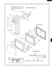
CONTROL PANEL PARTS
Control unit Control panel frame with key unit and LCD Key unit Liquid crystal display Rubber connector Screw;...OVEN PARTS
Latch hook Light mount plate Waterproof cushion Capacitor holder Fan blade Fan duct Oven...
AN
1
AN
1
AH R-204EWA
PARTS LIST
Note: The parts marked "∆" may cause undue microwave exposure. The parts marked "*" are used in...
Service Manual - Page 35
1
2
3
4
5
Befor attaching Control unit to
A
Control panel, foil side of Control
CONTROL PANEL PARTS
unit must be different than illustration.
1
2
3
4
5
33
E F G H 6 alcohol.
3-1
3-4
3-2
B
6-10
3-2-2
3-3
R-204EWA 6
A
B
C
D
3-2-1
C
DOOR PARTS
5-6
5-8
D
5-7
E
5-2 5-3
F
G
5-1 5-8
5-4
5-5
MISCELLANEOUS
6-4
6-5 6-6
H
Actual wire harness may be cleaned by ethyl-
Similar Questions

Flashing 00:00 & Now The Microwave Will Not Start Or Clear
(Posted by brickadams56 2 years ago)

Power Level Operation
How do I change the power level on this microwave? Pressing the power level button several times doe...
How do I change the power level on this microwave? Pressing the power level button several times doe...
(Posted by kagunders 9 years ago)

How To Remove The Control Panel On A Sharp R-820bk Microwave
(Posted by yeldojones6 9 years ago)

Clock Only Flashes. None Of The Buttons On Keypad Function
(Posted by norael125 11 years ago)

How Many Watts Is My R-204ewa Sharp Carousel Microwave
(Posted by Bkse9924 11 years ago)