Sharp LC-26SH10U Support Question
Sharp LC-26SH10U Support Question
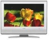
Find answers below for this question about Sharp LC-26SH10U - 26" LCD TV.Need a Sharp LC-26SH10U manual? We have 1 online manual for this item!
Question posted by dcorbitt54 on July 10th, 2015
Closed Caption Just Stopped Working
My service is from Directv in standard definition. It has a regular cable hookup. No HDMI Cables. The CC just stopped working.
Current Answers
Answer #1: Posted by TommyKervz on July 10th, 2015 3:21 AM
TommyKervz

Member since:
January 10th, 2013 Points: 17,776,833

Member since:
January 10th, 2013 Points: 17,776,833
Please refer on the link below for a solution.
Related Sharp LC-26SH10U Manual Pages
Service Manual - Page 1
... SOLDER (PbF A1-2 • GENERAL SPECIFICATIONS A2-1~A2-5 • DISASSEMBLY INSTRUCTIONS B1-1~B2-2 • SERVICE MODE LIST ...C-1 • WHEN REPLACING EEPROM (MEMORY) IC C-2 • RE-WRITE FOR DIGITAL SOFT ... to be used for after sales service only. The contents are subject to change without notice. #########
LCD COLOR TELEVISION
MODEL LC-26SH10U
In the interests of user-safety ...
Service Manual - Page 2
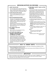
.... Especially as to deal with the printed board. Remove the antenna terminal on TV and turn
on the contact section of the heat sink. Insulation resistance between the...LCD PANEL
Avoid a shock to the IC and Transistor). Therefore, put in the original positions, or whether there are the portions which were removed in order to keep the indications and notices in your SERVICE...
Service Manual - Page 4
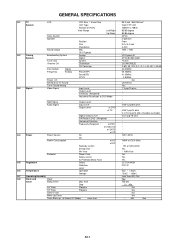
US System M
ATSC(8VSB)/QAM
1Tuner
US (W/CABLE)
2~69, 4A, A-5~A-1, A~I, J~W, W+1~W+84
44.00MHz
45.75MHz
41.25MHz
4.50MHz
No
US-Stereo
Yes
1 ...Less than
26.0 inch / 660.53mmV
Color TFT LCD
1366(H) x 768(V)
85/85 degree
85/85 degree
NTSC
2 Speaker
Front
2.2 x 5.0 inch
4 ohm
10W + 10W
---
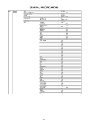
GENERAL SPECIFICATIONS
G-1 TV System
G-2 Tuning System
G-3 Signal
LCD
Color System ...
Service Manual - Page 5
...Format Custom Code Power Source
Total Keys Keys
Voltage(D.C) UM size x pcs
POWER FUNCTION Source POWER DISPLAY LIGHT SEARCH+ SEARCHPLAY REC STOP PAUSE SKIP+ SKIPVIEW MODE 1 2 3 4 5 6 7 8 9 0 . ENT INPUT FLASH BACK VOL+ VOLCH+ ... RIGHT UP DOWN EXIT RETURN FAVORITE A FAVORITE B FAVORITE C FAVORITE D FAVORITE SLEEP AUDIO AV MODE CC
RC-MQ No
SHARP SHARP 10000 / 10001 3V UM-3 x 2 pcs 40 Keys Yes
No No...
Service Manual - Page 6
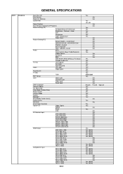
...Position
Auto Setup(Language/CH Program)
Picture Setting(TV)
AV Mode(Picture Preference)
Brightness , Contrast , Color
Tint
Sharpness
Color Temperature
Cable Clear
Picture Setting(PC)
BRIGHTNESS , CONTRAST
HOR...Air/Cable
ADD/DELETE
Label
CH Label
Video Label
Favorite CH
V-Chip
Type
RRT Setup
Lock
Hotel Lock
Channel Lock
Video Lock
Panel Lock
OSD Language
Closed Caption
CC ...
Service Manual - Page 7
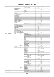
...Service Facility List Important Safeguard Dew/AHC Caution Sheet Quick Set-up Sheet Battery
AC Adapter
AC Cord (for AC Adapter)
AC Cord (Flat Polarity Plugs)
Cable... Menu Play Eject Skip+, Search+ Skip-, SearchStill/Pause Stop Main Power SW Input Select Main Power SW Power/Stand...2 (Variable) (L, R) RCA x 3 RCA x 2(L/MONO, R)
No No
HDMI x 1 RCA x 2(L/MONO, R)
No No No No No Coaxial No
F Type Yes
No ...
Service Manual - Page 10

Remove the LCD Cover in the direction of arrow (A). 3. Remove the LCD Panel in the direction of arrow (B).
11
1
21
1
2 1 1
2
21 (B)
LCD Cover
Front Cabinet (A)
LCD Panel
Fig. 1-4
B1-2 Remove the 4 screws 2. 4. Remove the 8 screws 1. 2. DISASSEMBLY INSTRUCTIONS
1-4: LCD COVER/LCD PANEL (Refer to Fig. 1-4)
1.
Service Manual - Page 13
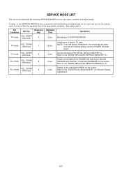
... main unit and on the remote control for more than the standard time in the appropriate condition. (See below chart.)
Set Condition
Set Key
Remocon Key
TV mode
VOL.
ALL mode
VOL.
SERVICE MODE LIST
This unit is provided with the following SERVICE MODES so you set factory initialization, the memories are reset
such...
Service Manual - Page 14
... value) + (16 x tens digit value) + (ones digit value)
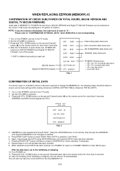
CONFIRMATION OF INITIAL DATA
If a service repair is now selected and should appear as FIG 2. ADDRESS is undertaken where it will now have the correct...will take you set . C-2
MICON Version Digital TV MICON Firmware
INIT : C66D ROM : 0000 ADC : 8F97 DVP1 : F8B4 *1 DVP2 : 2D23 LCD ON 0000 OEC7154B_010 DTV d0l63041
FIG. 1
Initial ...
Service Manual - Page 16
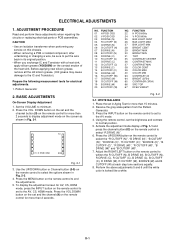
... FUNCTION 22 H POSI 60Hz 24 V POSI 60Hz 25 BAK LIGHT CENT 26 BAK LIGHT MAX 27 BAK LIGHT MIN 28 BRIGHT CENT 29 BRIGHT MAX ... adjustment screen for more than 2 seconds. TV
01 H POSI OSD
346
Fig. 2-1
3. DOWN button on the remote control to the AV, CS, HDMI mode. Adjust the RIGHT/LEFT button on the... any
service on the remote control for electrical adjustments. 1. Pattern Generator
2.
Service Manual - Page 17

...
26
26
26
56
---
---
26
56
---
---
55
D-2 Step No. Step No. Step No. ELECTRICAL ADJUSTMENTS
2-2: Confirmation of Fixed Value (Step No.)
Please check if the fixed values of each of the adjustment items are set correctly referring below. (TV/AV/CS/HD-MI)
CS
HD-MI
TV TV 720p AV AV (S) 480i 480p 720p 1080i 480i 480p...
Service Manual - Page 23
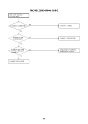
YES
IS DIGITAL PCB
NO
CONNECTED ?
THE STOP PICTURE "PLEASE WAIT". TROUBLESHOOTING GUIDE
NO IS CD3806 CONNECTED ?
E-5 YES
CHANGE DIGITAL PCB. CHECK Q512, IC509 AND PERIPHERAL CIRCUIT.
CONNECT DIGITAL PCB. YES
IS THERE VOLTAGE
NO
AT PINS 1 AND 2 OF
CD3806 5V ? CONNECT CD3806.
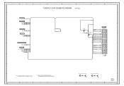
Service Manual - Page 26

LCD PANEL V2301
LK260T3LF12
EEPROM IC 256K IC103
AT24C256N-10 SU-2.7
6 EEP_SCL 5 EEP_SDA
EEPROM IC 256K IC104
AT24C256N-10 SU-2.7
6 EEP_SCL 5 EEP_SDA
POWR_ON-H
DTUNER RX DTUNER TX
...
Service Manual - Page 29

...4
2
3
L3608
ACM2012D
1
4
2
3
L3607
ACM2012D
1
4
2
3
L3606
ACM2012D
1
4
2
3
L3605
ACM2012D
1
4
2
3
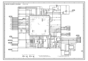
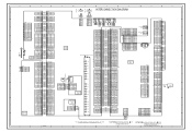
INTERFACE BLOCK DIAGRAM
HDMI INTERFACE IC3605 SiI9021CTU
29 DSDA1 30 DSCL1 31 DSDA0 32 DSCL0
39 R0XC40 R0XC+ 43 R0X044 R0X0+ 47 R0X148 R0X1+ 51 R0X252... HSYNC 2 VSYNC 3
SCK 86 WS 85 SD0 84 OVCC 5 OVCC 6 OVCC 26 OVCC 76 OVCC 89 OVCC 109 OVCC 122 OVCC 134 CSCL 28 CSDA 29 RESET#...
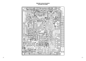
Service Manual - Page 33
...
C128
R134 R119 R122 R145 R146
R129 R118 R147
R148 R115 R197 R114 D105
R149
IC104
R141 R142
51 Q105 Q101
C131 C139
R163 R112
26
NR2104
NR2102
NR2103
NR2101
1 C863 C860 C857
C830 C883
C815
R2105 R2107
NR2105 NR2106
C2802
C8131
C8150
C2130
1
61
C2149
L8105
C2133
C8151
R2112
IC2101...
Service Manual - Page 39
...29
4.9
AFT
AFT
28
W876 4.9
LEVEL SHIFT Q4403 KRC102SRTK
AUDIO_MUTE
NC
27
NC
26
AUDIO_MUTE 25
0 0
SW_YUV_PB
EXT_MUTE-H 24
GND
23
SCART1_B 22
GND
21
SW_YUV_Y
...POWER_FAIL 11
POWER_ON-H
POWER_ON-H 10
AFT_1
AFT_1
9
VS_ON/LCDON
LCDON
8
4
NC DVB_FAN_ON-H 7
RLY_ON/LCD-H
LCD-H/PDP_RLY 6
NC
S_DET
5
SW_YUV1/2 PSU_5VD/DSR/LIGHT_CTL
NC
4
SW_YUV1/2 3
NC
2
LIGHT CTL/...
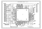
Service Manual - Page 46
...SD_SW1 P50/^WRL/^WR
NC
HDMI/DVI
SCALER_SW
YUV_SW
EPM
COMPONENT/HDMI
NC
HDMI_H
NC
DVB_RX
28 SDA1
DVB_TX (RST1)
27 SCL1
(CLK1)
26 NC
DVD_RX
DVD_TX
0 NC...NC 0 0 0 3.4 3.2 3.2 3.2
00
DVB_FAN_ON-H
0
R151
STEREO_RESET
10K
SCALER-H
SCALER_RESET R158
S_DET
SW_SCART IIC_OFF
R102 LCD-H AFT_1[LOW] AFT_2[HIGH] LCDON
AFT KEY-B KEY-A
DTUNER_H
R103 2.2K
R104 2.2K
C123 0.1 B 3.2
D101 C106...
Service Manual - Page 47
... DPR6 DPR5 DPR4 DPR3 DPR2 DPR1 DPR0
DPG7
22
AFT_1
23
LCDON
24 DVB_FAN_ON-H
25 LCD-H/PDP_RLY
26
S_DET
W824 W875
AFT_1[LOW] LCDON
DVB_FAN_ON-H LCD-H S_DET
DDHS
C824 0.1 B C836
SW_CVBS
C837
C883 0.1 B C838
3.4 3.4
0 ...20
GND
21 DTUNER_POWER
22
GND
23 DTUNER_SD_H
24
GND
25 SWITCH_CVBS
26
GND
27 SWITCH_VIDEO_Y
28
GND
29 SWITCH_VIDEO_C
DVB_POWER_CTL-H
SD_H W931
W802
W930...
Service Manual - Page 49
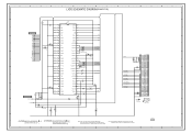
...
18
RXIN2-
19
RXIN2+ 20
GND
21
RXCLK IN- 22
RXCLK IN+ 23
GND
24
RXIN3-
25
RXIN3+ 26
GND
27
NC VDD+3.3V/NC/GND 28
NC VDD+3.3V/NC/GND 29
NC/GND 30
VDD+3.3V/GND 31...
GND
32
CD7204 CHRU3002
LCD PANEL
V2301 LK260T3LF12
C7219 4V330 V-S
C7208 6.3V 220 V-S
C7209 6.3V 220 V-S
GND
1
CAUTION:SINCE THESE PARTS MARKED ...
Service Manual - Page 63
...11
5
CLK+
10
NC DVB_FAN_ON-H 7 7
24 24 DVB_FAN_ON-H
D0-
9
CP2403
CP5801(CP2403)
NC
1 OOB
LCD-H/PDP_RLY 6 6
NC
S_DET
55
25 25 LCD-H/PDP_RLY
26 26
S_DET
SCALER PCB PCBDS0
D0-S
8
D0+
7
UNREG+5V 1
1 UNREG+5V
2 +5V
44
27 27
...
GND
18 18
12 12
GND
CP102
VDD+3.3V/NC/GND 10 TO LCD PANEL
AFT(0) 19
19 AFT_1
GND
2
2
GND
SW_AUDIO_L(PC) 17 17
13 13 SW_AUDIO_L(PC)
GND
1...
Similar Questions

Replacement Screws For Stand
Replacement screws for Sharp LC-26SH10U stand...
Replacement screws for Sharp LC-26SH10U stand...
(Posted by johnnie0402 8 years ago)

How Do I Assemble Tv Stand
assembly of tv stand for sharp tv lc26sh10u
assembly of tv stand for sharp tv lc26sh10u
(Posted by Littlenurseja 8 years ago)

Want To Get Rid Of Closed Captions On My Lc52le700yun Sharp Aquos Tv
(Posted by bbouroutzis 9 years ago)

Sharp Lc26sh10u Tv Manual
I want to mount the tv on a wall mount. Where are the correct holes to place the screws? I see 2 of ...
I want to mount the tv on a wall mount. Where are the correct holes to place the screws? I see 2 of ...
(Posted by rvsquared 10 years ago)
I Cant Get The Closed Caption To Shut Off On My Tv
(Posted by bluke 13 years ago)