Sharp LC-26SH10U Support Question
Sharp LC-26SH10U Support Question
Find answers below for this question about Sharp LC-26SH10U - 26" LCD TV.Need a Sharp LC-26SH10U manual? We have 1 online manual for this item!
Question posted by Littlenurseja on July 31st, 2015
How Do I Assemble Tv Stand
assembly of tv stand for sharp tv lc26sh10u
Current Answers
Answer #1: Posted by TechSupport101 on July 31st, 2015 6:41 PM
TechSupport101

Member since:
May 24th, 2013 Points: 12,171,305

Member since:
May 24th, 2013 Points: 12,171,305
Related Sharp LC-26SH10U Manual Pages
Service Manual - Page 2
... is replaced should be found on the TV. 3. and DESCRIPTION You can be used .
4.
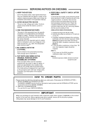
KEEP THE NOTICES
As for safety. BE CAREFUL WITH THE LCD PANEL
Avoid a shock to the IC and Transistor... and Transistor with the printed board. PUT PARTS AND WIRES IN THE ORIGINAL POSITION AFTER ASSEMBLING OR WIRING There are indicated with it in the operation manual.
2. Make sure to service...
Service Manual - Page 4
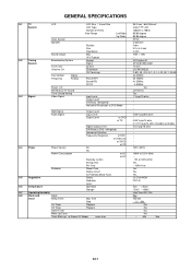
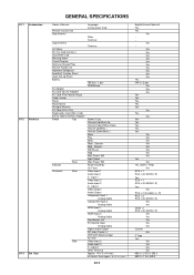
...Preset CH Stereo/Dual TV Sound Tuner Sound Muting Video Signal
LCD Size / Visual Size LCD Type Number of Pixels ...G-4 Power
Power Source
AC
DC
Power Consumption
at AC
at DC
Stand by (at AC)
Energy Star
Per Year
Protector
Power Fuse
Safety ...IC
--
0oC ~ +40oC
-20oC ~ +60oC
Less than
26.0 inch / 660.53mmV
Color TFT LCD
1366(H) x 768(V)
85/85 degree
85/85 degree
NTSC
2 Speaker
Front...
Service Manual - Page 6
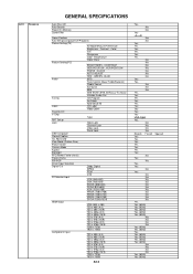
...Comb Filter
Game Position
Auto Setup(Language/CH Program)
Picture Setting(TV)
AV Mode(Picture Preference)
Brightness , Contrast , Color
Tint
Sharpness
Color Temperature
Cable Clear
Picture Setting(PC)
BRIGHTNESS , CONTRAST
... CH
V-Chip
Type
RRT Setup
Lock
Hotel Lock
Channel Lock
Video Lock
Panel Lock
OSD Language
Closed Caption
CC Advanced
View Mode (Picture Size)
Picture...
Service Manual - Page 7
...Sheet Quick Set-up Sheet Battery
AC Adapter
AC Cord (for AC Adapter)
AC Cord (Flat Polarity Plugs)
Cable Cramp
Stand
Stand Screw
Hexagon Wrench
AV Cord (2Pin-1Pin)
Registration Card (NDL Card)
300 to 75ohm ...+ Skip-, SearchStill/Pause Stop Main Power SW Input Select Main Power SW Power/Stand-By On Timer Video Input 1 Audio Input 1 S - Input 1 Video Input 2 Audio Input 2 S - W x D x H (...
Service Manual - Page 8
...container)
Cabinet
Front
Rear
Jack Panel
PCB
Non-Halogen Demand
Eyelet ...Material G-17 Environment
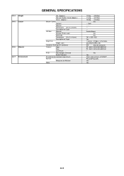
GENERAL SPECIFICATIONS
Net (Approx.)
Net w/o Handle, Stand (Approx.)
Gross (Approx.)
Master Carton
Content
Material
Dimensions W x D x ... Photo Label
W/Handle
Dimensions W x D x H(mm)
Description of SHARP
Phase3(Phase3A)
Yes
Yes
A2-5
Double/Brown
No
No
781 x 255...
Service Manual - Page 9

... the DigitalPCB and AV PCB in the direction of
arrow (C). 10.
Disconnect the following connectors:
(CP301, CP302, CP2403, CP2404, CP4202). 8. Remove the 2 screws 4. 11. Fig. 1-1
1-2: STAND ASS'Y/ANGLE BACK 1/2/PLATE JACK 1/2 (Refer to Fig. 1-1)
1. BOARDS
1-1: BACK CABINET (Refer to Fig. 1-2)
1. Remove the 4 screws 2. 4. REMOVAL OF MECHANICAL PARTS AND P.C. Remove the Back...
Service Manual - Page 10

DISASSEMBLY INSTRUCTIONS
1-4: LCD COVER/LCD PANEL (Refer to Fig. 1-4)
1. Remove the 8 screws 1. 2. Remove the 4 screws 2. 4. Remove the LCD Panel in the direction of arrow (B).
11
1
21
1
2 1 1
2
21 (B)
LCD Cover
Front Cabinet (A)
LCD Panel
Fig. 1-4
B1-2 Remove the LCD Cover in the direction of arrow (A). 3.
Service Manual - Page 13
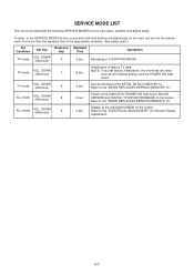
... main unit and on the screen. DOWN (Minimum)
9
2 sec.
Initialization of MEMORY IC. DOWN (Minimum)
6
2 sec. ALL mode
VOL. C-1 DOWN (Minimum)
0
Standard Time
Operations
2 sec. TV mode
VOL.
DOWN (Minimum)
1
2 sec.
ALL mode
VOL. Display of the Adjustment MENU on the remote control for more than the standard time in the...
Service Manual - Page 14
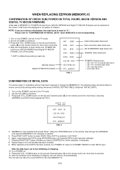
... the VOLUME to INITIAL SETTING TABLE (Attached "INITIAL DATA").
1.
ADDRESS and DATA should "blink". ADDRESS DATA
INIT 0000 00
LCD ON 0000
OEC7154B_010
DTV d0l63041
FIG. 2
4. ADDRESS is reset to the TV mode. 2. Press RIGHT/LEFT button to finish DATA input. When DATA is undertaken where it will turn POWER off automatically...
Service Manual - Page 16
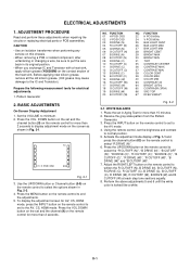
...adjustments when repairing the circuits or replacing electrical parts or PCB assemblies.
Use the UP/DOWN button or Channel button (0-9) on...22 H POSI 60Hz 24 V POSI 60Hz 25 BAK LIGHT CENT 26 BAK LIGHT MAX 27 BAK LIGHT MIN 28 BRIGHT CENT 29 BRIGHT... the above adjustments 5 and 6 until the white color is looked like a white. TV
01 H POSI OSD
346
Fig. 2-1
3. Set the VOLUME to set in Fig...
Service Manual - Page 17

... of each of the adjustment items are set correctly referring below. (TV/AV/CS/HD-MI)
CS
HD-MI
TV TV 720p AV AV (S) 480i 480p 720p 1080i 480i 480p 720p 1080i ...
43
43
43
---
---
43
43
---
---
43
66 SRC TOP(S.STRECH)
26
26
26
26
26
26
---
---
26
26
---
---
26
67 DEFA VIMGVT(STRECH)
20
25
20
20
20
43
26
24
20
44
32
24
42
67 DEFA VIMGVT(SIDE BAR)
20
25
20
20...
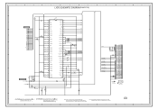
Service Manual - Page 26

...
58
53
MICON
27
IC101
OEC7154B 28
74 90 17 89 10 14 33 34
LVDS IC IC7201 ICSV385AGLFT
TX OUT0~3+ TX OUT0~3TXCLKOUT+ TXCLKOUT- LCD PANEL V2301
LK260T3LF12
EEPROM IC 256K IC103
AT24C256N-10 SU-2.7
6 EEP_SCL 5 EEP_SDA
EEPROM IC 256K IC104
AT24C256N-10 SU-2.7
6 EEP_SCL 5 EEP_SDA
POWR_ON-H
DTUNER RX DTUNER TX...
Service Manual - Page 39
...29
4.9
AFT
AFT
28
W876 4.9
LEVEL SHIFT Q4403 KRC102SRTK
AUDIO_MUTE
NC
27
NC
26
AUDIO_MUTE 25
0 0
SW_YUV_PB
EXT_MUTE-H 24
GND
23
SCART1_B 22
GND
21
SW_YUV_Y
...POWER_FAIL 11
POWER_ON-H
POWER_ON-H 10
AFT_1
AFT_1
9
VS_ON/LCDON
LCDON
8
4
NC DVB_FAN_ON-H 7
RLY_ON/LCD-H
LCD-H/PDP_RLY 6
NC
S_DET
5
SW_YUV1/2 PSU_5VD/DSR/LIGHT_CTL
NC
4
SW_YUV1/2 3
NC
2
LIGHT CTL/...
Service Manual - Page 46
... 0 0 0 3.4 3.2 3.2 3.2
00
DVB_FAN_ON-H
0
R151
STEREO_RESET
10K
SCALER-H
SCALER_RESET R158
S_DET
SW_SCART IIC_OFF
R102 LCD-H AFT_1[LOW] AFT_2[HIGH] LCDON
AFT KEY-B KEY-A
DTUNER_H
R103 2.2K
R104 2.2K
C123 0.1 B 3.2
D101...
YUV_SW
EPM
COMPONENT/HDMI
NC
HDMI_H
NC
DVB_RX
28 SDA1
DVB_TX (RST1)
27 SCL1
(CLK1)
26 NC
DVD_RX
DVD_TX
0 NC
0 NC
0 JG102
0 JG105
0 JG106
0
0
R119
0
...
Service Manual - Page 47
... DPR6 DPR5 DPR4 DPR3 DPR2 DPR1 DPR0
DPG7
22
AFT_1
23
LCDON
24 DVB_FAN_ON-H
25 LCD-H/PDP_RLY
26
S_DET
W824 W875
AFT_1[LOW] LCDON
DVB_FAN_ON-H LCD-H S_DET
DDHS
C824 0.1 B C836
SW_CVBS
C837
C883 0.1 B C838
3.4 3.4
0 ...20
GND
21 DTUNER_POWER
22
GND
23 DTUNER_SD_H
24
GND
25 SWITCH_CVBS
26
GND
27 SWITCH_VIDEO_Y
28
GND
29 SWITCH_VIDEO_C
DVB_POWER_CTL-H
SD_H W931
W802
W930...
Service Manual - Page 49
...
18
RXIN2-
19
RXIN2+ 20
GND
21
RXCLK IN- 22
RXCLK IN+ 23
GND
24
RXIN3-
25
RXIN3+ 26
GND
27
NC VDD+3.3V/NC/GND 28
NC VDD+3.3V/NC/GND 29
NC/GND 30
VDD+3.3V/GND 31...
GND
32
CD7204 CHRU3002
LCD PANEL
V2301 LK260T3LF12
C7219 4V330 V-S
C7208 6.3V 220 V-S
C7209 6.3V 220 V-S
GND
1
CAUTION:SINCE THESE PARTS MARKED ...
Service Manual - Page 63
...11
5
CLK+
10
NC DVB_FAN_ON-H 7 7
24 24 DVB_FAN_ON-H
D0-
9
CP2403
CP5801(CP2403)
NC
1 OOB
LCD-H/PDP_RLY 6 6
NC
S_DET
55
25 25 LCD-H/PDP_RLY
26 26
S_DET
SCALER PCB PCBDS0
D0-S
8
D0+
7
UNREG+5V 1
1 UNREG+5V
2 +5V
44
27 27
...
GND
18 18
12 12
GND
CP102
VDD+3.3V/NC/GND 10 TO LCD PANEL
AFT(0) 19
19 AFT_1
GND
2
2
GND
SW_AUDIO_L(PC) 17 17
13 13 SW_AUDIO_L(PC)
GND
1...
Service Manual - Page 69
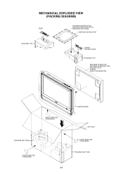
MECHANICAL EXPLODED VIEW (PACKING DIAGRAM)
TM101
POLYBAG INSTRUCTION, INSTRUCTION BOOK (E/F/S), REGISTRATION CARD
INSTRUCTION BOOK KIT
PACKAGE TOP
CD3810 HOLDER CORD
PACKAGE TOP
PACKAGE STAND-TOP PACKAGE STAND-BOTTOM PACKING SACK SCREW SHEET INFORMATION
SHEET BARCODE (7230008183)
PACKAGE BOTTOM
SHEET BARCODE (7230008182)
J-3
LAMIFILM BAG
GIFT BOX SHEET BARCODE (7230008183) PACKAGE BOTTOM
Service Manual - Page 70

MECHANICAL EXPLODED VIEW (PACKING DIAGRAM)
PACKAGE STAND-TOP
SHEET INFORMATION
PACKING SACK (791WHA0126)
SCREW
PACKING SACK (791WHA0125)
PACKAGE STAND-BOTTOM
J-4
Service Manual - Page 71
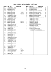
J3Y00417A REGISTRATION CARD(SHARP)
--- JA4ND200 POLYBAG INSTRUCTION(RED CAUTION)
K1-1
A3Y004E975 INSTRUCTION BOOK KIT
...7290000172 800WFA0063
STAND ASS'Y STAND ANGLE STAND SHEET CAUTION CUSHION LEG
105
752WSA0555 SHIELD DIGITAL
106
752WSA0556 DIGITAL SHIELD COVER
107
752WSA0575 SHIELD SCALER
108
753WEA0030 SHEET CU
109
753WEA0035 SHEET CU
110
761WSA0374 COVER LCD
111
...
Similar Questions

Replacement Screws For Stand
Replacement screws for Sharp LC-26SH10U stand...
Replacement screws for Sharp LC-26SH10U stand...
(Posted by johnnie0402 8 years ago)

Sharp Lc26sh10u Tv Manual
I want to mount the tv on a wall mount. Where are the correct holes to place the screws? I see 2 of ...
I want to mount the tv on a wall mount. Where are the correct holes to place the screws? I see 2 of ...
(Posted by rvsquared 10 years ago)

Flat Panel Lc20b4u-sm Is Broken.
Can I replace a broke flat panel lc 20b4u-sm
Can I replace a broke flat panel lc 20b4u-sm
(Posted by Mbermudezford 10 years ago)


Sharp 26' Lcd Lc-26sb24u
I have a shrp 26" LCD tv model LC-26SB24U the the green light will come on for about 15-20 sec. then...
I have a shrp 26" LCD tv model LC-26SB24U the the green light will come on for about 15-20 sec. then...
(Posted by awoliver86 12 years ago)