
Sharp LC-15AV7U Support Question
Sharp LC-15AV7U Support Question
Find answers below for this question about Sharp LC-15AV7U.Need a Sharp LC-15AV7U manual? We have 1 online manual for this item!
Question posted by pawwlw on September 16th, 2011
Need Another Stand
I have misplaced my stand and need another one. Where could I purchase one?
Current Answers
Answer #1: Posted by TVDan on September 16th, 2011 7:01 PM
TVDan

Member since:
August 8th, 2011 Points: 4,732,000

Member since:
August 8th, 2011 Points: 4,732,000
Related Sharp LC-15AV7U Manual Pages
Service Manual - Page 1

...CABINET DISASSEMBLY INSTRUCTIONS 4-1 ELECTRICAL ADJUSTMENT INSTRUCTIONS 5-1 HOW TO INITIALIZE THE LCD TELEVISION 6-1 TROUBLESHOOTING ...7-1 BLOCK DIAGRAMS ...8-1 SCHEMATIC DIAGRAMS/ CBA'S AND TEST POINTS ... to those specified be used .
MODEL LC-15AV7U SERVICE MANUAL
LCD COLOR TV
LC-15AV7U
SERVICE MANUAL
S17F1LC15AV7U
LCD COLOR TV
MODEL LC-15AV7U
In the interests of user-safety (Required...
Service Manual - Page 2
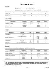
...Sound 41.25 MHZ
Description 1. Audio S/N
Condition
Unit
80dB
dB
80dB
dB
Nominal ----- Over Scan
2. Description 1. Limit --------- Limit 0.8/0.8 3.0/3.0
---->45/45 >45/45
The LCD panel is not to provide many years of Pixels 2. Number of useful life. Resolution 4. Response
4. Limit -------
±0.005 ±0.005
------- Video S/N 2. Color Temperature
3. Audio S/N
Condition...
Service Manual - Page 4

...any exposed metal parts that there are not limited to, (1) spacing between the Liquid Crystal Panel and the cabinet mask, (2) excessively wide cabinet ventilation slots, and (3) an improperly fitted ...the coaxial connector. With the instrument AC switch first in the on the Liquid Crystal Panel. 3.
IMPORTANT SAFEGUARDS AND PRECAUTIONS
Prior to shipment from the factory, our products are ...
Service Manual - Page 6

... having a return to make certain that leads are not pinched, and check that no modification of completing these special safety characteristics are identified in LCD television have special safety-related characteristics. electrical components having such features are often not evident from visual inspection, nor can protection afforded by them be identical...
Service Manual - Page 9

... a fine tip soldering iron or hot air blower, pull up the wire as the solder melts so as shown in Fig. S-1-6)
Caution: 1. S-1-2)
2. when removing entire flat pack-IC, first apply soldering iron to the CBA; S-1-3)
(2) Affix the wire to break or damage the foil of each lead of the...
Service Manual - Page 10

... from the CBA using a soldering iron, care must be taken to center of the pins have solder bridges. (4) Bottom of the flat pack-IC on the CBA so you can install a replacement flat pack-IC more easily.
(2) The " " mark on the PCB when positioning for installation. S1-8.)
(3) Solder all pins of the...
Service Manual - Page 12

... CBA
D2 Desolder
---
[15]
Speaker (s)
D2
4(S-13), Speaker Holder (s)
---
[16]
Front Cabinet
D2
---
[17] Front Cover D2
---
2. Part No.
[1]
Arm Assembly
[2]
Stand Cover
[3]
Rear Cabinet
[4]
Function CBA
[5]
Tilt Stand Holder
Removal Remove/*Unhook/ Fig. Note: (1) Order of steps in reverse order. No. No. Part
Removal
Remove/*Unhook/
Fig. Unplug/Unclamp/
Desolder...
Service Manual - Page 13

D1
4-2
A7121DC [3] Rear Cabinet
(S-3)
(S-3)
(S-3)
[2] Stand Cover
(S-4) (S-3)
(S-1)
[1] Arm Assembly
(S-2)
(S-2)
Fig.
Service Manual - Page 14

...)
[10] LCD Holder
(S-11)
(S-10)
(S-11) [9] Main CBA
[6] IR Sensor CBA
Speaker Holder (S-13)
[13] Junction-A CBA
(S-11) (S-10)
(S-11)
(S-10)
(S-10) (S-9)
(S-6)
(S-9)
[7] Jack Holder
(S-8) (S-9)
[5] Tilt Stand Holder
(S-9) (S-9)
Module PCB Holder
[8] DTV Module CBA Unit
Fig. D2
4-3
A7121DC
Service Manual - Page 17

...adjustment normally are not attempted in a darkroom. Only when replacing the LCD Panel then adjust as shown above signal.
2. [RF/INPUT1]
Press [MENU...the service mode. Symptom of Misadjustment: If Sub-Brightness is incorrect, proper brightness cannot be set perpendicularly to the LCD Panel surface. 4. [RF/INPUT1] Enter the service mode. EQ.
[RF/INPUT1] C/D1
[INPUT2] C/D2
White Purity ...
Service Manual - Page 18
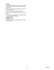
Confirm "C" position was beginning to bright, no need to bright.
5. If "C" position is not available or to initial position.
4. [INPUT2]
Press [MENU] button on the remote control unit and press [3] on the TV ...
Service Manual - Page 19

Confirm "FF" indication on the TV unit simultaneously in the standby mode.
2. To enter the service mode, press [MENU] and [POWER] buttons on the upper right of the screen.
6-1
A7121INT HOW TO INITIALIZE THE LCD TELEVISION
1. To initialize the LCD television, press [DISPLAY] button on the remote control unit.
3.
Service Manual - Page 20

... not output.
7-2
6 VT+33V is not output.
7-3
7 INV+22V is not output.
7-3
8 DTV-ON+3.3V is not output.
7-3
9 DTV-ON+2.5V is not output.
7-3
10 PANEL+3.3V is not output.
7-3
11 DTV-ON+5V is not output.
7-4
12 AL+3.3V(D) is not output.
7-4
13 AL+1.2V(D) is not output.
7-4
14 AL...
Service Manual - Page 22

FLOW CHART NO.10 PANEL+3.3V is not output. No Is approximately 5V voltage supplied to the
No
cathode of D901? Yes Check IC906 and the periphery circuit, and service ...
Service Manual - Page 34

...(1)
IC906 +3.3V REG.
Q909 SW+2.5V
D924 SHUNT REG. IC904 +1.8V REG. Q916 SWITCHING
+35V VT+33V
DTV-ON-H P-ON-H
CN1202
CN1402 CN1411
1~9 PANEL+3.3V 17~25
1~2 PANEL+3.3V
TO SYSTEM CONTROL BLOCK DIAGRAM
LVDS CBA UNIT
TO LCD MODULE
A7121BLP
Q901 SW+3.3V
AL+1.2V(D) AL+3.3V(D) AL+3.3V(A)
IC905 +5V...
Service Manual - Page 52
...
CN1301 1 2 3 4
CN1411 1 2 3 4 5 6 7 8 9 10 11 12 13 14 15 16 17 18 19 20
PANEL+3.3V PANEL+3.3V GND GND TA(-) TA(+) GND TB(-) TB(+) GND TC(-) TC(+) GND TCLK(-) TCLK(+) GND TD(-) TD(+) GND NU
BACK LIGHT
BACK... 2
CN403 1 2
LVDS CBA UNIT
CN1402 25 PANEL+3.3V 24 PANEL+3.3V 23 PANEL+3.3V 22 PANEL+3.3V 21 PANEL+3.3V 20 PANEL+3.3V 19 PANEL+3.3V 18 PANEL+3.3V 17 PANEL+3.3V 16 GND 15 GND 14 GND 13 QBL...
Service Manual - Page 54

... QBL[1]
Pixel Data Output (QBL)
117 QBL[0]
Pixel Data Output (QBL)
118 VSS
GND
119 VSS
GND
120 VSS
GND
121 VSS
GND
122 LPF
Panel Clock PLL Filter
123 NU
Not Used
124 NU
Not Used
125 QCLKL
Clock Signal Output
126 QGL[7]
Pixel Data Output (QGL)
12-2
A7121PIN
Service Manual - Page 73

LC-15AV7U
COPYRIGHT © 2007 BY SHARP CORPORATION
ALL RIGHTS RESERVED.
Feb. 2007 Printed in any form or by any means, electronic, mechanical, photocopying, recording, or otherwise, without prior written permission of this publication may be reproduced, stored in a retrieval system, or transmitted in USA
SHARP ELECTRONICS CORPORATION 1 No part of the publisher.
Similar Questions

My Sharp Aquos 32' Tv Has No Picture Or Sound.
MY SHARP AQUOS 32" TV(LC-32LE450U) has no picture or sound.The green lgt is on thats located on the ...
MY SHARP AQUOS 32" TV(LC-32LE450U) has no picture or sound.The green lgt is on thats located on the ...
(Posted by fsheffield 7 years ago)

Flat Panel Lc20b4u-sm Is Broken.
Can I replace a broke flat panel lc 20b4u-sm
Can I replace a broke flat panel lc 20b4u-sm
(Posted by Mbermudezford 11 years ago)

My Sharp Lcd Television Lc -37hv4m Won't Turn On Red Light Blinking
(Posted by Anonymous-74776 11 years ago)

Where Can I Purchase A Lcd Screen For My Lc-46sb54u Flat Panel Tv Brand Is Shar
(Posted by allwayswillbe 12 years ago)

How Do You Fix A Green Line On A Sharp Lcd Panel Model Lc-45gd6u?
(Posted by ppearson 13 years ago)