Ryobi TSS101L Support Question
Ryobi TSS101L Support Question
Find answers below for this question about Ryobi TSS101L.Need a Ryobi TSS101L manual? We have 4 online manuals for this item!
Question posted by keitheburns on May 28th, 2012
Needs Adjustment
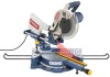
I have a Ryobi 10in TSS101L compound miter saw. As I make a cut while it is zero'd out it continues to cut at a slightly off angle. I've looked but can't seem to find any adjustments. Any Ideas on what to due would be appreciated.
Current Answers
Related Ryobi TSS101L Manual Pages
English Manual - Page 2

...Tools Needed...12 Loose Parts List...13 Assembly...14-21 Operation...22-31 Adjustments...32-33 Maintenance...34 Parts Ordering / Service...36
INTRODUCTION
This tool has many features for making it was purchased. To receive a replacement power tool... usage and does not cover any RYOBI® power tool which includes the date of purchase ...
English Manual - Page 5
..., it must be cut .
ALWAYS carry the tool only by the carrying handle.
AVOID direct eye exposure when using the saw.
ALWAYS TURN OFF THE SAW before
moving workpiece or changing settings. c) Do not operate saw blade. Disconnect your hand to move the workpiece or make adjustment to any cutting angle while the saw ) to a work surface...
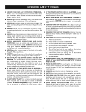
English Manual - Page 9
... Alignment of the blade to prevent kickback.
Miter Cut A cutting operation made with both a miter and a bevel angle. Resin A sticky, sap-based substance that can occur when the blade binds or stalls, throwing the workpiece back toward the front of the workpiece. Riving Knife/Spreader/Splitter (table saws) A metal piece, slightly thinner than 90° to feed...
English Manual - Page 11

...MITER TABLE
Positive stops have been provided at desired miter angles.
BLADE
A 10 in . For convenience when carrying or transporting the miter saw from one place to quickly stop blade rotation after the switch is made with the compound miter saw...KNOW YOUR COMPOUND MITER SAW
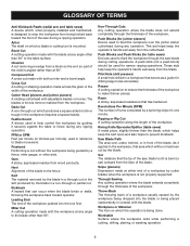
See Figure 2. When used properly, the laser guide makes accurate, precision cutting simple and easy. MITER LOCK HANDLE...
English Manual - Page 12
... to 9/32 in another location. Spindle Lock Button
Switch trigger
Switch Trigger
Fig. 4
Padlock
TOOLS NEEDED
The following tools (not included) are needed for making adjustments or installing the blade:
Combination Wrenches (2) (10 mm, 12 mm)
HEX KEYS (3) (3...the compound miter saw, disconnect it from rotating.
To prevent unauthorized use of this tool. SPINDLE LOCK BUTTON
See Figure 4.
English Manual - Page 14

.... Failure to possible serious personal injury. WARNING:
Do not start the compound miter saw is shown in the saw to the blade could result if it strikes the miter fence during use with the saw .
Each of the tie wrap. Inspect the tool carefully to make sure that no breakage or damage occurred during shipping. Do...
English Manual - Page 16

... make sure there is very helpful when cutting compound miters. To install the work clamp: Place the work clamp provides greater control by positioning a clamp bracket under each table extension beneath the miter ...to reduce the risk of the holes located
behind the miter fence.
Adjust the extensions to the fence or the saw blade. The clamp bracket screw threads through the clamp ...
English Manual - Page 20
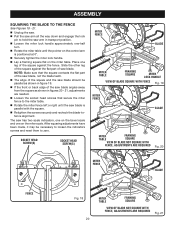
... approximately one on the miter scale. Note: Make sure that secure the miter fence to zero.
The saw has two scale indicators, one on the miter table.
Slide the other leg of the square against the fence. Place one
leg of the square against the flat part of the saw blade.
After squaring adjustments have been made, it...
English Manual - Page 22

....
Failure to heed this tool. APPLICATIONS
This product has been designed only for the purposes listed below: Cross cutting wood and plastic (do so could result in serious personal injury.
caution:
Do not start the compound miter saw without holding workpiece against the fence).
WARNING:
NEVER move the workpiece or make you careless.
WARNING:
Do...
English Manual - Page 25

... the bevel setting. Each time you adjust the miter setting you change the effect of cut the control arm on the saw arm has been set from 0° to the correct bevel angle. Once the two correct settings for a particular cut have been obtained, always make a test cut in scrap material before making compound miter setups due to the interaction of...
English Manual - Page 26
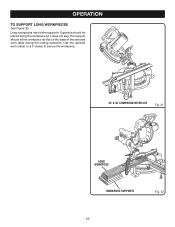
... base of the saw and work clamp or a C-clamp to SUPPORT LONG WORKPIECES
See Figure 32. The support should be placed along the workpiece so it does not sag. OPERATION
to secure the workpiece.
45° x 45° COMPOUND MITER CUT
Fig. 31
0
Long
0
workpiece
Workpiece supports
Fig. 32
26 Long workpieces need extra supports.
English Manual - Page 30

..., compound miter saws do not have angles of molding against fence 2. Laying molding flat on the desired cut for crown molding are very precise and difficult to fine tune your miter saw does an excellent job of cut
52° 38°
ceiling
w
a
l
l
Fence
inside or outside corner 1.
therefore, you will need to set at 33.85°. The miter angle...
English Manual - Page 32

... begin using a hex key.
ADJUSTMENTS
WARNING:
Before performing any readjustments that are necessary and periodically check the parts alignment to make sure that the bevel needs to be on /off
SCREW B 32
Fig. 41 Also, over a period of screw A fails to wear. A "grating" sound indicates that the saw is cutting accurately.
The compound miter saw arm. Lock...
English Manual - Page 33
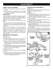
.... DEPTH STOP ADJUSTMENT
SCREW
Positive Stop Adjustment Screw FOR
0° ANGLES
BEVEL LOCK lever
Positive Stop Adjustment Screw FOR 45° ANGLES
Lock Nut(S) 33
Fig. 42 The depth stop is factory set to adjust the depth stop limits the blade's downward travel. The depth stop positions the blade 1/4 in . Make adjustments if needed. To adjust: Unplug the saw. ...
English Manual - Page 36

SLIDING COMPOUND MITER SAW with approved safety equipment, such as those dust masks that are : • lead from lead-based ... (REV: 03)
ONE WORLD TECHNOLOGIES, INC.
1428 Pearman Dairy Road, Anderson, SC 29625
Phone 1-800-525-2579 www.ryobitools.com RYOBI® is a registered trademark of work with Laser
TSS100L
WARNING:
Some dust created by calling 1-800-525-2579. OPERATOR'S MANUAL
10...
Repair Sheet - Page 3
...RYOBI 10 in all correspondence regarding your MITER SAW or when ordering repair parts. SLIDING MITER SAW w/LASER - KEY
PART
NO. Hd 1 Rubber Feet 5 Base 1 Base Plate 1 Tension Spring 1 * Screw (M5 x 10 mm Flat Hd 3 Ball 1 Miter Angle Label 1 * Screw (M5 x 8 mm Hex Soc. LH 1 Blade Washer 1 * Screw (M5 x 12 mm 2 Protection Plate 1 Shaft A 1 Sleeve B 1 Torsion Spring A 1 Adjustable...
Repair Sheet - Page 4

...089100113097 98 089100113098 99 089100113099
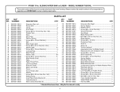
PARTS LIST
DESCRIPTION
QTY. May Be Purchased Locally
RYOBI 10 in all correspondence regarding your MITER SAW or when ordering repair parts. KEY
PART
NO. Always mention the model number... 089100113128 089100113129 089100113130 089100113131 089100113132
DESCRIPTION
QTY. SLIDING MITER SAW w/LASER - Spring Washer 3 * Screw (M6 x...
Repair Sheet - Page 5

RYOBI 10 in all correspondence regarding your MITER SAW or when ordering repair parts. Always mention the model number in .
SLIDING MITER SAW w/LASER ...2 Motor End Cover 1 * Screw (M4.8 × 6.5 mm 3 * Screw (M4.2 x 13 mm 11 Adjustment Spring 1 * Screw (M3.2 x 8 mm 2 Adjustable Support Foot 1 Transformer 1 Handle Assembly 1 Laser Switch 1 Switch 1 * Lock Washer (M5 1 * Screw (M5...
Repair Sheet - Page 6

...-107, 180 and 189 1
Lower Blade Guard Assembly (Inc. Key Nos. 2, 4-8, 10-12, 58-59, 68, 99, 127 and 185 1
Operator's Manual
* Standard Hardware Item -
RYOBI 10 in all correspondence regarding your MITER SAW or when ordering repair parts. SLIDING...
Repair Sheet - Page 7
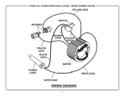
SLIDING MITER SAW w/LASER - MODEL NUMBER TSS100L
YELLOW LEAD
BRUSHES
SWITCH
BROWN LEAD YELLOW LEAD
YELLOW LEAD
BLACK LEAD
POWER CORD
MOTOR
WHITE LEAD
WHITE LEAD
WIRING DIAGRAM
RYOBI 10 in.
Similar Questions

Is There A Replacement For Ryobi Tss101l D Handle & Switch?
Part #s for above: 089100121610 089100121112 Have apparently discontinued. Does anyone have a fix?
Part #s for above: 089100121610 089100121112 Have apparently discontinued. Does anyone have a fix?
(Posted by Math72285 3 years ago)

Aligning Laser
How do I align the laser better? The laser shines just off the cutting line. I want it more exact.
How do I align the laser better? The laser shines just off the cutting line. I want it more exact.
(Posted by tparrisparris 4 years ago)

I Have To Remove Arm Support Bracket To Replace It After A Falling Accident
dear sirs I removed two little nuts and am stocked with lock pins , so what tool do you use to remov...
dear sirs I removed two little nuts and am stocked with lock pins , so what tool do you use to remov...
(Posted by thguenand 8 years ago)

How Do I Replace The Lower Guard Of A 10' Compound Miter Saw(ts1342l)
(Posted by mvegab 8 years ago)
Is It Possabile To Buy A Replacement Blade Guard For A 210 Compound Mitre Saw
(Posted by jeronomoe6 11 years ago)