
Pioneer PRO-607PU Support Question
Pioneer PRO-607PU Support Question
Find answers below for this question about Pioneer PRO-607PU.Need a Pioneer PRO-607PU manual? We have 1 online manual for this item!
Question posted by rbrown7784 on November 23rd, 2012
Replaced Main Board Now Sypmtoms Are Solid Red And Blue Led's
Original problem was 12 blue flashes which said to replace main board. Did that, no joy
Current Answers
Answer #1: Posted by jcweidick on November 11th, 2017 7:23 PM
jcweidick

Member since:
November 11th, 2017 Points: 0
Member since:
November 11th, 2017 Points: 0
Related Pioneer PRO-607PU Manual Pages
Service Manual - Page 1
...Haven 1087, Keetberglaan 1, 9120 Melsele, Belgium PIONEER ELECTRONICS ASIACENTRE PTE. ARP3400
PLASMA DISPLAY
PRO-607PU
THIS MANUAL IS APPLICABLE TO THE FOLLOWING MODEL(S) AND TYPE(S). PCB CONNECTION ...PARTS 2 2. BLOCK DIAGRAM AND SCHEMATIC DIAGRAM 10
2.1 OVERALL WIRING DIAGRAM 10 2.2 HNM BLOCK DIAGRAM 12 2.3 CONNECTOR PIN DESCRIPTION 13 2.4 HN MODULE ASSY (1/6 14 2.5 HN MODULE ASSY (2/6 18 ...
Service Manual - Page 2
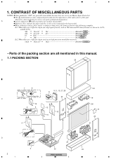
... are not in the service manual for noise filter Bead band x3
23
C
16
2
5
12
15
18
15
17
1 D
4
3
2 1
20
22
PRO-607HD
2
3
24 19 26
10 23 21
24 4 in our Master Spare Parts List. Therefore, when replacing, be sure to mark on some component parts indicates the importance of the safety...
Service Manual - Page 4
...:
A
Part No. Mark
Symbol and Description
PDP-6071PU KUCXC
PRO-607PU KUCXC
Remarks
P21 - 1
P21 - 2 P21 - 3 P11 - 2
NSP
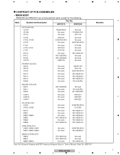
PCB ASSEMBLIES 1..MAIN Assy
1..IO Assy 2..TANSHI ASSY 2..POD ASSY 2..SIDE ASSY...ASSEMBLIES, Refer to " CONTRAST OF PCB ASSEMBLIES ". : The numbers in the remarks column correspond to "Replacement of AWV2311: HOME NETWORK MODULE Assy"
No.1 No.2 No.3 No.4 No.5 No.6 No.7
P11 ...
Service Manual - Page 6
...M17
D CN7802
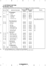
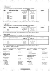
Figure B: AWV2311-B /J
6
PRO-607HD
1
2
3
4 B /J
J7601: ADX3483
yes
no
CN7802: KM200NA3L
no
yes
Connection with MAIN ass'y Figure A
Figure B
When AWV2311-A ...MAIN ass'y
When AWV2311-B /J is used in the product, replace the defective ass'y with a service parts ass'y as shown in Figure B. Solder it with MAIN ass'y as shown in Figure B.
1
2
3
4
Replacement...
Service Manual - Page 7
ARP3395"
Remarks
PRO-607HD
5
6
7
8
A B C D 7 AWV2312... used
UPA1917TE 2SC4116
CKSSYB104K10
RS1/16SS102J RS1/16SS223J RS1/16SS104J RS1/10S0R0J
[BOARD IF BLOCK] R4031 R4011 R4032
CN4011 CN4016 CN4017
RS1/16SS0R0J Not used ..., C4946, C4947 R4901, R4902, R4904
Not used Not used
CKSRYB105K10 RS1/16SS220J
[MAIN UCOM BLOCK] R8454 R8470 R8469, R8453
RS1/16SS103J RS1/16SS103J
Not used
Not used...
Service Manual - Page 8
...(U)] SEMICONDUCTORS
IC7701,7702
MISCELLANEOUS F 7701
RESISTORS R 7709,7710 R 7711-7718 Other Resistors
DCH1201 CCSSCH7R0D50 CKSSYF104Z16
EDD2516AKTA-6B
ATL7002
RS1/16SS1001F RAB4CQ560J RS1/16SS###J
8
PRO-607HD
1
2
3
4 Refer to "Service Manual: Order No. Refer to "Service Manual: Order No.
Refer to " 2.4 - 2-9 Schematic Diagram and 3. Description
Part No.
AWW1156
AWW1153...
Service Manual - Page 10
1
2
3
4
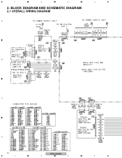
2. BLOCK DIAGRAM AND SCHEMATIC DIAGRAM
2.1 OVERALL WIRING DIAGRAM
A
B
C
D
10
PRO-607HD
1
2
3
4
Service Manual - Page 11
5
6
7
8
A
B
for AWV2311-A
for AWV2311-B
PRO-607HD
5
6
7
C
D 11 8
Service Manual - Page 12
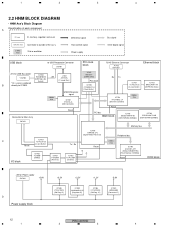
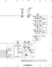
... X'tal
Connector to IC7803. IC]
IC7901 LM2664M6X [Converter IC]
12
PRO-607HD
1
2
3
4 mode filter]
B
directly to Main Ass'y
Reset
PCI bus
8620 block
IC7701 EDD2516AKTA-6B [DDR-SDRAM... PST596IN [Reset IC]
IC7852 TC74LCX04
[Inverter]
Reset
27MHz X'tal
IC7703 AGC1027-A-PI (S29GL128N90TFIR2) [Flash Memory (128Mbit)]
Reset
DDR block
+5V for USB Bus-power
*CN7802
* Or, a wire...
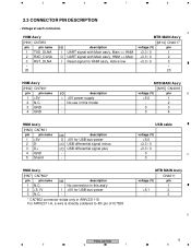
Service Manual - Page 13
...
pin name
1 N.C.
2 +5.1V
3 N.C. For AWV2311-A, a wire is directly soldered to 4th pin of IC78.03
MTB MAIN Ass'y
CN4011
voltage (V)
pin
-
1
+5.1
2
-
3
D
PRO-607HD
13
5
6
7
8 No use in AWV2311-B. I /O USB differential signal plus
-
- MTB MAIN Ass'y
[M15] CN4016
voltage (V)
pin
B
+5.0
1
-
2
0
3
0
4
HNM Ass'y
[HN3] CN7801
pin
pin name
1 +5V
2 D-
3 D+
4 GND...
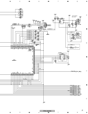
Service Manual - Page 23
5
6
7
8
A
USB POWER SECTION
B
C
D
PRO-607HD
23
5
6
7
8
Service Manual - Page 28
... for respective destinations, be sure to check with resistor
DGS
D G SD G S
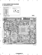
Field effect transistor
P.C.Board Chip Part SIDE B
Resistor array
3-terminal regulator
• HN MODULE ASSY
B
4 SIDE A
C
D
28 1
PRO-607HD
2
3
(ANP2148B) 4 1
2
3
3. A comparison between the main parts of PCB diagrams.
Connector Capacitor
BCE
Transistor B C EB C E
SIDE A
BCE
Transistor with the...
Service Manual - Page 30
...
IP Address: 192.168.201.1
one .
30
PRO-607HD
1
2
3
4
Replace the HNM ass'y with another
one .
ethernet terminal. yes
There may be connected before the PDP's power-on "HOME MENU" GUI be selected? yes
No
Note: One of the supported video format is the main menu of the server, check the server operation...
Service Manual - Page 31
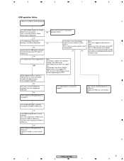
...USB device available, can not be displayed! There may be something defective in the device displayed? D
PRO-607HD
31
5
6
7
8 Then, is the URL from which can be something defective in ... be selected? Below is the main menu of 720p resolution are not supported by this . For example, most of the SONY digital cameras
are available.
Replace the HNM ass'y with another one...
Service Manual - Page 32
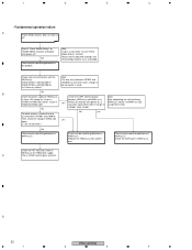
... power supply for about 40 seconds until "Home Media Gallery" turns selectable.
Replace the HNM ass'y with the MAIN ass'y. [HN1]CN7851[M14]CN4017 [HN2]CN7901[M15]CN4016 Isn't there any pulse...on , is used.
D
32
PRO-607HD
1
2
3
4 1
2
3
4
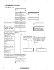
• Fundamental operation failure
A
"Home Media Gallery" does not work at all!
Check the UART path in
MAIN ass'y for HNM power supply....
Service Manual - Page 33
5
6
7
8
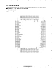
5. IC INFORMATION
• The information shown in the list is basic information and may not correspond exactly to that shown in the schematic diagrams.
RTL8100CL-LF (HN MODULE Assy: IC7754)
A
• Ethernet Controller IC
Pin Arrangement
B
C
D
PRO-607HD
33
5
6
7
8
Similar Questions

Pioneer 5080hd Tv Stand
I need the part number or model number for the original tv stand that came with my Pioneer 5080HD tv...
I need the part number or model number for the original tv stand that came with my Pioneer 5080HD tv...
(Posted by paulpribyl1562 1 year ago)

Pioneer Elite Pro-607pu Weight
What is thePioneer Elite PRO-607PU WeightWhere can I buy factory stand?
What is thePioneer Elite PRO-607PU WeightWhere can I buy factory stand?
(Posted by ipurchaser 3 years ago)

Pioneer Pro607pu Plasma Tv
Where can I purchase a table top stand for the Pioneer PRO607PU 60" Plasma TV
Where can I purchase a table top stand for the Pioneer PRO607PU 60" Plasma TV
(Posted by bordergon3 6 years ago)

Pdp-5010 Has No Power
my pioneer pdp5010 is receiving no power,, there is a click when power is plugged in initially, then...
my pioneer pdp5010 is receiving no power,, there is a click when power is plugged in initially, then...
(Posted by bravo0789 8 years ago)

Blue Light Around Volume Control No Longer Turns Off
I have an x-cm30 home stereo. when it is on there is a blue light around the volume contro. The li...
I have an x-cm30 home stereo. when it is on there is a blue light around the volume contro. The li...
(Posted by wfrench 11 years ago)