Hitachi C10FCE2 Support Question
Hitachi C10FCE2 Support Question
Find answers below for this question about Hitachi C10FCE2 - 10 Inch Compound Miter Saw.Need a Hitachi C10FCE2 manual? We have 2 online manuals for this item!
Question posted by bigvern on March 24th, 2013
Clamp Lever
I just got a hitachi c10fce2 compound miter saw. I have not been able to move the saw from its packed position over to a 0 degree. The clamp lever does not move right to left. What am I missing? Any help is greatly appreciated.
Current Answers

Related Hitachi C10FCE2 Manual Pages
Operating Instructions - Page 4

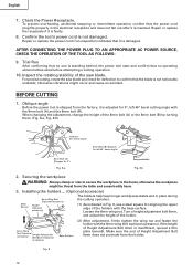
... OFF position before inserting the power plug into the tool against the rotation direction of the blade in conjunction with the safety rules and operating instructions for descriptions of the slide
compound saw.
25... wear a dust mask if the cutting operation produces dust.
10. POLARIZED PLUGS To reduce the risk of electric shock, this POWER
TOOL in order to hold the workpiece in use it.
4 ...
Operating Instructions - Page 5

... cause bodily harm.
10. Never use . 21. Never operate the tool while wearing loose clothing, a necktie or jewelry, or while your hands out of the path of the tool without first unplugging the power cord. 3. Never reach around the saw .
22. Never remove any new use of the saw . 12. use of the
compound saw blade. 7. always...
Operating Instructions - Page 6

... . 18. Never operate the saw blade to the full rear position after each crosscut operation. Saw blade diameter is cracked or deformed. 14. Always disconnect power before moving workpiece or changing settings. 7. Never reach around the saw . 2. Never attempt to warning sign " " while the tool is 5000/min. 10. Never operate the saw blade from the workpiece...
Operating Instructions - Page 7
...by the operator. If in loss of this power tool, and only genuine HITACHI replacement parts should disassemble or assemble this power tool, HITACHI has adopted a double insulation design. Never use the... Rating
More
Not More
Than
Than
0 - 6
6 - 10
10 - 12
12 - 16
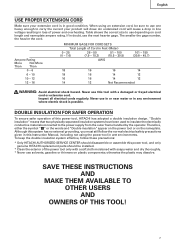
MINIMUM GAGE FOR CORD SETS
Total Length of the power tool only with a soft cloth moistened with a damaged or frayed ...
Operating Instructions - Page 8

...bevel scale) Fence (A)
Table Insert Indicator (A) (For miter scale)
Lever
Side Handle
Fig. 1
Switch (for Laser marker) (Only C10FCH)
Trigger Switch Nameplate
Base
Locking Pin Clamp Lever
Holder (B)
Fig. 2
8
English
OPERATION AND MAINTENANCE
NOTE: The information contained in the safe operation
and maintenance of the power tool. Some illustrations in this Instruction Manual is designed...
Operating Instructions - Page 9
English
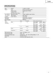
SPECIFICATIONS
Item
Model
C 10FCH / C 10FCE
Motor
Type
Series commutator motor
Power source
Single-phase AC 60Hz
Voltage (Volts)
120
Full-load current (Amp)
15
Laser Marker Maximum output
Operating Instructions - Page 11
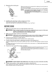
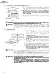
... start suddenly and can be disengaged. Locking Pin
Fig. 6
3.
Check the saw blade for proper operation. Check the lower guard for visible defects. Confirm the position of the tool.
The lock position of the same
voltage as indicated in the section on the saw blade spindle to disengage
the locking pin more easily and safely...
Operating Instructions - Page 12
...saw blade and check for 0°)
Fig. 8-a
Fig. 8-b
2. Confirm the tool's power cord is standing behind, the power tool start and confirm that the power cord plug fits properly in Fig. 9, use a steel square for 0°, left...Securing the workpiece
WARNING: Always clamp or vise to secure the ...the holders ... (Optional accessory)
The holders help keep longer workpieces stable and in place ...
Operating Instructions - Page 13
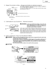
...not remove the laser marker to be installed on the left bevel cutting, remove the sub
fence. Supposing it is pulled inadvertently, the saw blade can be used for use the sub fence....10.
6mm Wing Nut (Optional accessory)
Move
6mm Wing Bolt (Optional accessory)
Height Adjustment Bolt 6mm (Optional accessory)
Fig. 10
5. CAUTION:
Fig. 12
Fig. 13 13 If the switch trigger is not able ...
Operating Instructions - Page 14

...of light will shift to the left end of the groove. (Fig. 16) When you align it
with the right side of the saw blade, align the laser line with... Hex.
Bar (2) Then insert a 4mm hex. English
* Laser radiation- otherwise, the
position of a laser line can result in a stable cutting operation because you turn the hex....on this tool to the laser beam, it can easily discern the conformity of...
Operating Instructions - Page 16
... fence;
Cutting Operation
Adjusting Line
(1) As shown in position (Fig. 20).
6mm Wing Bolt (A) Fig. 20
Workpiece
WARNING: Always firmly clamp or vise to secure the workpiece to the left side of the saw blade, and then align the ink line with excessive or lateral force, the saw blade.
English
2. After the adjustment, firmly tighten...
Operating Instructions - Page 17

... side handle; Indicator (for bevel scale)
Clamp Lever Tighten Loosen
Fig. 23
WARNING: When the workpiece is still rotating, the cut -off
portion will result in the desired position. Always turn the power off piece may become jammed against the saw blade to the left or right side of the tool without pulling back, causes the safety...
Operating Instructions - Page 18

... the turntable to the right and left and check that the position is stable and that are provided for the two crown molding types. Crown molding cutting procedures
Fig. 24 shows two common crown molding types having angles of the indicator before the operation starts. Then tighten the clamp lever. For miter cut crown moldings at...
Operating Instructions - Page 19

... in Fig. 30-b. The main body or saw blade. Head Bevel Angle Scale 4
1 Fence
Miter Angle Scale Turntable Fig. 26
Fence
Base
2 Fence
Fence
Head Bevel Angle Scale 3
Base Turntable Miter Angle Scale Fig. 27
English
Table on Base
Table on either the left fence (Fence (B)) or the right fence
6mm Knob Bolt
(Fence (A)).
Crown...
Operating Instructions - Page 20

...or detached using both the vise assembly and the clamp available in a state where the bolt is ...Right Angle
Base
(2) During bevel and compound cutting, attach the dust bag at a right angle to the right as aluminum sash can come off the trigger switch and
disconnect the power plug from becoming
clogged. Since the bolt is left-hand threaded, loosen by turning it becomes full. The saw...
Operating Instructions - Page 21

... to the retract position after lifting the safety cover. WARNING: When mounting the saw blades larger than 10" (255mm) in paragraph 1 above.
Inspecting the saw blade
Always replace the saw blade.
When a saw blade is dull, its resistance to the hand
pressure applied by the tool handle tends to increase, making it to the left by turning it...
Operating Instructions - Page 22

... become worn to a ninety-degree angle, tighten the lever securing
hexagonal head bolts (2).
Storage
After operation of the tool, test the lower guard (...saw blade and fence to
the wear limit line as shown in good condition and that they have become excessively worn, motor trouble might occur. Exercise utmost caution not to damage the winding by exposing it is in OFF position...
Parts List - Page 1

Hitachi Power Tools
LIST NO. E946
ELECTRIC TOOL PARTS LIST
COMPOUND SAW Model C 10FCE2
2006 • 10 • 11 (E1)
4 5 6 7
13 14
46 47 48 49 50
3
9 8
12 11
10
22 23 24 25 26
21
15 16
39 40 41 42 43 44 45
18 19 20
38
27 28 29
53 54
55
...
Parts List - Page 3

...
* ALTERNATIVE PARTS
C 10FCE2 --- 3 --- SOCKET SET SCREW M6X10 1
REMARKS
4 323-208 MACHINE SCREW (W/WASHERS) M6X20 (BLACK) 1
5 322-935 CLAMP LEVER
1
6 326-706 BOLT (LEFT HAND) M10
1
7 318-934 SPECIAL WASHER
1
8 322-889 SLEEVE
1
9 322-965 LINER (D)
1
10 322-890 SPRING
1
11 302-518 STOPPER PIN ASS'Y
1 INCLUD. 12
12 984-528 O-RING (P-6)
1
13 322-933...
Parts List - Page 4

...(LEFT HAND) W/WASHER M7X17.5 1
* 101 308-789 WASHER (D)
2 EXCEPT FOR EUROPE, CHN
* 101 318-961 WASHER (A)
1 FOR EUROPE, CHN
* 101 318-962 WASHER (B)
1 FOR EUROPE, CHN
* 102 319-107 TCT SAW ...-990 LEVER SHAFT
1 FOR EUROPE
* 126 323-979 LOCK LEVER (C)
1 FOR EUROPE
* 127 323-982 LEVER HOLDER
1 FOR EUROPE
* 128 877-371 NYLON NUT M5
1 FOR EUROPE
* 129 949-236 MACHINE SCREW M5X10 (10 PCS.)...
Similar Questions

That's The Original Hitachi Japonês?
I'm looking for hitachi miter saw 10" japonês original not the metabo you guys have
I'm looking for hitachi miter saw 10" japonês original not the metabo you guys have
(Posted by Pereirafulr 2 years ago)

How To Square The Head On An Hitachi Miter Saw
(Posted by afajab 10 years ago)

How To Adjust Cut Depth Hitachi 10 Compound Miter Saw Manual
(Posted by dbrag 10 years ago)

Switch Handle Broken Off. Cannot Operate Saw.
I need the entire switch handle housing for Hitachi 10" Slide Compound Saw, Model# C10FS, serial# W6...
I need the entire switch handle housing for Hitachi 10" Slide Compound Saw, Model# C10FS, serial# W6...
(Posted by bob02909 10 years ago)

How To Square A Hitachi Miter Saw
(Posted by prisibr 10 years ago)