
Dell PowerEdge 1900 Support Question
Dell PowerEdge 1900 Support Question
Find answers below for this question about Dell PowerEdge 1900.Need a Dell PowerEdge 1900 manual? We have 7 online manuals for this item!
Question posted by tricite on January 18th, 2014
How To Test A Dell Poweredge 1900 Power Supply
The person who posted this question about this Dell product did not include a detailed explanation. Please use the "Request More Information" button to the right if more details would help you to answer this question.
Current Answers
Related Dell PowerEdge 1900 Manual Pages
Getting Started Guide - Page 5

...that signals the appropriate systems management software if the top cover is opened.
• An 800-W power supply.
• Six system cooling fans. NOTE: If you decide to upgrade your system include: &#... of your system by installing a second processor, you must order the processor upgrade kits from Dell contains the correct version of the processor and heat sink.
• A minimum of 512 ...
Getting Started Guide - Page 9
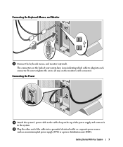
... each connector. Plug the other end of your system have icons indicating which cable to plug into a grounded electrical outlet or a separate power source such as an uninterrupted power supply (UPS) or a power distribution unit (PDU). The connectors on the monitor's cable connector.
Connecting the Keyboard, Mouse, and Monitor
Connect the keyboard, mouse, and...
Getting Started Guide - Page 12
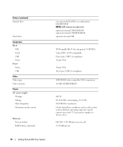
...and over the entire system ambient operating range, the inrush current may reach 55 A per power supply for integrated 1-GB NIC) 9-pin, DTE, 16550-compatible Four 4-pin, USB 2.0-compliant...
Connectors Back
NIC Serial USB Video Front Video USB
Video Video type Video memory
Power AC power supply
Wattage Voltage Heat dissipation Maximum inrush current
Batteries System battery RAID battery (optional)
...
Hardware Owner's Manual (PDF) - Page 4
...
Opening and Closing the System 46 Removing the Bezel 46 Installing the Bezel 47 Opening the System 48 Closing the System 48
Power Supply 50 Removing the Power Supply 50 Installing the Power Supply 51
Fans 52 Removing and Installing a Fan 53 Removing and Installing the Cooling Shroud Fan 54
Expansion Cards 56 Installing an Expansion...
Hardware Owner's Manual (PDF) - Page 6
... 105 Troubleshooting a USB Device 105 Troubleshooting a NIC 106 Troubleshooting a Wet System 106 Troubleshooting a Damaged System 107 Troubleshooting the System Battery 108 Troubleshooting the Power Supply 108 Troubleshooting System Cooling Problems 109 Troubleshooting a Fan 109 Troubleshooting System Memory 110 Troubleshooting a Diskette Drive 112 Troubleshooting an Optical Drive 113...
Hardware Owner's Manual (PDF) - Page 12

... turned off the system using the end of these buttons is pressed. The power button controls the DC power supply output to locate a particular system within a rack. NOTE: If you turn off immediately after the power button is pushed, the LCD panel on the front and the blue system status indicator on .
Both the...
Hardware Owner's Manual (PDF) - Page 14
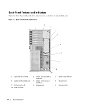
... and Indicators 1
2 3
4 5
6 7
8
1 expansion-card slots (6)
4 system identification button
7 USB connectors (4) 10 serial connector
10
2 remote access connector (optional)
5 system status indicator connector
8 power supply
9
3 system status indicator 6 NIC connector 9 video connector
14
About Your System Back-Panel Features and Indicators
Figure 1-2 shows the controls, indicators, and...
Hardware Owner's Manual (PDF) - Page 18
....
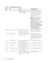
machine check error.
If the problem persists, ensure
that your system's Getting Started Guide.
Power supply voltage is
cleared using either Server
Assistant or the BMC Management
Utility.
Ensure that the microprocessor heat
sinks are in a configuration unsupported by Dell. The system BIOS has reported a See "Getting Help" on page 108. The system BIOS...
Hardware Owner's Manual (PDF) - Page 19
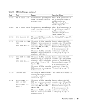
... reseat the PCI expansion cards.
If the problem persists, see "Troubleshooting Expansion Cards" on page 117. Check the AC power source for specified power supply is faulty. PS # Input Range
Power source for the specified power supply. I /O Channel Chk The system BIOS has reported an See "Getting Help" on a component that resides in slot #.
If the...
Hardware Owner's Manual (PDF) - Page 85
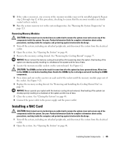
...CAUTION: Only trained service technicians are firmly seated in their sockets.
14 Run the system memory test in the system diagnostics. See "Removing the Cooling Shroud" on page 48. 3 Remove the...the Cooling Shroud Fan" on page 121. CAUTION: The DIMMs are authorized to the power supply and the power outlet. Installing a RAC Card
CAUTION: Only trained service technicians are hot to cool ...
Hardware Owner's Manual (PDF) - Page 107
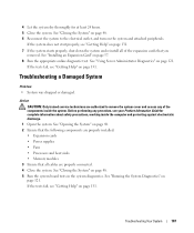
...starts properly, shut down the system and reinstall all cables are properly installed:
• Expansion cards • Power supplies • Fans • Processors and heat sinks • Memory modules 3 Ensure that the following components are... discharge.
1 Open the system. See "Using Server Administrator Diagnostics" on page 48. 5 Run the system board tests in the system diagnostics.
Hardware Owner's Manual (PDF) - Page 159
... even after you turn off your system, the POST tests various system components such as a diskette drive or keyboard...called partitions with software or hardware, that provides electrical power to implement: • A memory address space of ... in ROM include the program that allows operating systems to servers and storage systems in protected mode. Peripheral Component Interconnect. ...
Hardware Owner's Manual (PDF) - Page 161
...and browsing.
Watt(s). Windows Server 2003 - Zero insertion force.
Universal Serial Bus. A program used to connect to the host server. Volt(s) direct current.
...resolution, you start -up and down. Uninterruptible power supply. A video adapter may be integrated into an expansion slot. W - Windows Powered - V - An integrated and complete Microsoft Windows...
Hardware Owner's Manual (PDF) - Page 165
...
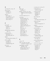
peripheral bay optical drive, 70 tape backup unit, 68
POST accessing system features, 10
power supply installing, 51 removing, 50 troubleshooting, 108
processor replacing, 88
R
RAC card installing, 85...startup accessing system features, 10
status messages LCD, 16 systems management, 23
support contacting Dell, 136
system board connectors, 127 installing, 99 jumpers, 125 removing, 97
system cooling...
Information Update - Page 1
Dell™ PowerEdge™ 1900 Systems
Information Update
www.dell.com | support.dell.com
Installing a SATA Optical Drive - Page 1
Dell™ PowerEdge™ 19x0 and 29x0 Systems
Installing a SATA Optical Drive
Installing a SATA Optical Drive - Page 3

...the data and power cables from the front of the bay.
7 For systems with the system.
b Remove the center fans and the center fan bracket. Installing a SATA Optical Drive
These instructions apply to Dell™ PowerEdge™ systems to... optical drive from the back of the optical drive.
6 PowerEdge 2900 and 1900 systems only: Perform the following steps. Installing a SATA Optical Drive
3
Installing a SATA Optical Drive - Page 6

... the optical drive kit.
4 Route the SATA cable to the power supply bays. b Bend the cable toward the chipset shroud and insert the cable into position.
2 Connect the SATA cable (the end with a cable provided in a PowerEdge 1950 Drive Tray 2 3
1 4
5
1 optical drive 3 SATA power cable 5 optical drive carrier
2 SATA cable 4 carrier latch
Installing the...
Installing a SATA Optical Drive - Page 7

...the SAS cable.
See "SAS Controller Daughter Card" in the PowerEdge 1950 2
1
3
4
6
5
1 SATA data cable 3 chipset shroud 5 SATA power cable
2 SATA_A connector on the system and attached peripherals.
Installing the SATA Optical Drive - Installing a SATA Optical Drive
7 SATA Cable Routing in your Hardware Owner's Manual.
7 Reconnect the system to the power supply connector.
Installing a SATA Optical Drive - Page 9

... Reconnect the system to an available power supply cable.
5 Replace the center fan bracket. Installing a SATA Optical Drive
9 See "Closing the System" in your Hardware Owner's Manual.
10 Close the system. For a PowerEdge 2900, use the SATA_D connector. Installing the SATA Optical Drive - For a PowerEdge 1900 system, connect to power and turn on the system board...
Similar Questions

Power Supply Nd444
Hi, i need the electronic schematic of ND 444 power supply. Can someone help me? Thanks. Renato....
Hi, i need the electronic schematic of ND 444 power supply. Can someone help me? Thanks. Renato....
(Posted by bragionr 9 years ago)


How Can I Turn On The Poweredge 6850 Power Supply Alone, Without Any Server?
(Posted by rocketclemens 12 years ago)