
Dell PowerEdge 1900 Support Question
Dell PowerEdge 1900 Support Question
Find answers below for this question about Dell PowerEdge 1900.Need a Dell PowerEdge 1900 manual? We have 7 online manuals for this item!
Question posted by cyharjay on March 3rd, 2014
Dell Poweredge 1900 Will Not Power On
The person who posted this question about this Dell product did not include a detailed explanation. Please use the "Request More Information" button to the right if more details would help you to answer this question.
Current Answers
Related Dell PowerEdge 1900 Manual Pages
Hardware Owner's Manual (PDF) - Page 2
...in this document is strictly forbidden. Reproduction in any proprietary interest in this text: Dell, the DELL logo, Inspiron, Dell Precision, Dimension, OptiPlex, Latitude, PowerEdge, PowerVault, PowerApp, PowerConnect, XPS, and Dell OpenManage are registered trademarks of Dell Inc. CAUTION: A CAUTION indicates a potential for property damage, personal injury, or death. Intel, Pentium...
Hardware Owner's Manual (PDF) - Page 18
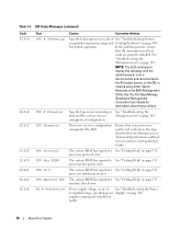
... unsupported by Dell. processor bus parity error.
If the problem persists, ensure
that your system's Getting Started Guide. See the Dell OpenManage
Baseboard ...page 108. machine check error.
unsupported configuration. processor initialization error. Power supply voltage is
cleared using either Server
Assistant or the BMC Management
Utility. Processors are properly installed. The...
Hardware Owner's Manual (PDF) - Page 139
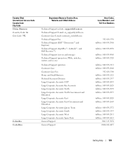
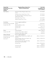
... and E-Mail Address
Technical Support website: support.dell.com.cn Technical Support E-mail: cn_support@dell.com Customer Care E-mail: customer_cn@dell.com Technical Support Fax Technical Support (Dell™ Dimension™ and Inspiron) Technical Support (OptiPlex™, Latitude™, and Dell Precision™) Technical Support (servers and storage) Technical Support (projectors, PDAs...
Hardware Owner's Manual (PDF) - Page 142
... Support
Guyana
General Support
Hong Kong
Website: support.ap.dell.com
International Access Code: 001 Technical Support E-mail: HK_support@Dell.com
Country Code: 852
Technical Support (Dimension and Inspiron)
Technical Support (OptiPlex, Latitude, and Dell Precision)
Technical Support (PowerApp™, PowerEdge™, PowerConnect™, and PowerVault™)
Customer Care
Large...
Hardware Owner's Manual (PDF) - Page 146
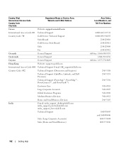
...Fax Technical Support Customer Service (Xiamen, China) Transaction Sales (Xiamen, China) Website: support.ap.dell.com Technical Support (Dell Precision, OptiPlex, and Latitude) Technical Support (Dimension, Inspiron, and Electronics and Accessories) Technical Support (PowerApp, PowerEdge, PowerConnect, and PowerVault) Customer Care
Transaction Sales Corporate Sales
Area Codes, Local Numbers, and...
Hardware Owner's Manual (PDF) - Page 149
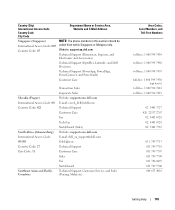
... in this section should be called from within Singapore or Malaysia only. Website: support.ap.dell.com
Technical Support (Dimension, Inspiron, and Electronics and Accessories)
Technical Support (OptiPlex, Latitude, and Dell Precision)
Technical Support (PowerApp, PowerEdge, PowerConnect, and PowerVault)
Customer Care
Slovakia (Prague) International Access Code: 00 Country Code: 421
South...
Hardware Owner's Manual (PDF) - Page 151
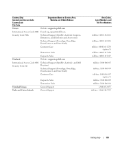
..., PowerConnect, and PowerVault)
Customer Care
Transaction Sales
Corporate Sales
Thailand
Website: support.ap.dell.com
International Access Code: 001 Country Code: 66
Technical Support (OptiPlex, Latitude, and Dell Precision)
Technical Support (PowerApp, PowerEdge, PowerConnect, and PowerVault)
Customer Care
Trinidad/Tobago Turks and Caicos Islands
Corporate Sales Transaction Sales...
Hardware Owner's Manual (PDF) - Page 156
...Subdirectories may contain additional directories branching off the root directory are defined as the power button and power indicator. DMI enables the management of groups and attributes that are limited to ...is made up of your network server using a remote access controller.
ERA allows you start the program for peripherals, such as www.dell.com, into an expansion-card ...
Hardware Owner's Manual (PDF) - Page 165
...56
peripheral bay optical drive, 70 tape backup unit, 68
POST accessing system features, 10
power supply installing, 51 removing, 50 troubleshooting, 108
processor replacing, 88
R
RAC card installing...
startup accessing system features, 10
status messages LCD, 16 systems management, 23
support contacting Dell, 136
system board connectors, 127 installing, 99 jumpers, 125 removing, 97
system cooling ...
Information Update - Page 1
Dell™ PowerEdge™ 1900 Systems
Information Update
www.dell.com | support.dell.com
Information Update - Page 2
...interest in any manner whatsoever without notice. © 2006-2009 Dell Inc. May 2009
P/N FF602
Rev. is subject to change without...of these materials in trademarks and trade names other than its own. Dell Inc. Reproduction of Dell Inc. Notes, Notices, and Cautions
NOTE: A NOTE indicates important...damage to hardware or loss of Dell Inc.; Other trademarks and trade names may be used ...
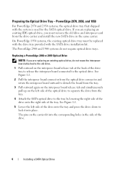
Installing a SATA Optical Drive - Page 1
Dell™ PowerEdge™ 19x0 and 29x0 Systems
Installing a SATA Optical Drive
Installing a SATA Optical Drive - Page 3

...a SATA Optical Drive
These instructions apply to Dell™ PowerEdge™ systems to remove the system cover ...and access any of the components inside the system.
See your Hardware Owner's Manual.
5 Disconnect the data and power...the back of the optical drive.
6 PowerEdge 2900 and 1900 systems only: Perform the following steps. Removing...
Installing a SATA Optical Drive - Page 4
....
The pins on the left side of the drive.
4
Installing a SATA Optical Drive The PowerEdge 2900 and 1900 systems do not reuse the interposer board attached to the old drive.
1 Pull outward on the...with the drive tray provided with the system is used for the SATA optical drive. Replacing a PowerEdge 2950 or 2970 Optical Drive
NOTE: If you are replacing an existing IDE optical drive, you...
Installing a SATA Optical Drive - Page 5

Figure 1-1. See Figure 1-2.
Installing a SATA Optical Drive
5 Replacing the Optical Drive in a PowerEdge 2950 or 2970 System
2 1
3
4
5
6
7
1 optical drive 3 interposer 5 SATA power cable 7 optical drive carrier
2 interposer release latch 4 SATA cable 6 carrier latch
Replacing a PowerEdge 1950 Optical Drive
NOTE: The replacement drive tray provided in the side of the drive.
...
Installing a SATA Optical Drive - Page 6

.... b Bend the cable toward the chipset shroud and insert the cable into position.
2 Connect the SATA cable (the end with a cable provided in a PowerEdge 1950 Drive Tray 2 3
1 4
5
1 optical drive 3 SATA power cable 5 optical drive carrier
2 SATA cable 4 carrier latch
Installing the SATA Optical Drive - NOTE: You may need to replace the existing...
Installing a SATA Optical Drive - Page 7

... board 4 system fans 6 optical drive
5 Reinstall the SAS controller daughter card and reconnect the SAS cable. See "Closing the System" in the PowerEdge 1950 2
1
3
4
6
5
1 SATA data cable 3 chipset shroud 5 SATA power cable
2 SATA_A connector on the system and attached peripherals. Figure 1-3. See "SAS Controller Daughter Card" in your Hardware Owner's Manual.
7 Reconnect...
Installing a SATA Optical Drive - Page 8

...cable to the SATA_B connector on system board 2 cable retention bracket
3 SATA data cable
4 SATA power cable
5 optical drive
8
Installing a SATA Optical Drive
See "Removing the Cooling Shroud" in your...the bracket detaches from the chassis slots.
6 Route the SATA cable in the cable channel in the PowerEdge 2950 and 2970
1
2
3 4 5
1 SATA_B connector on the system board. Figure 1-4. ...
Installing a SATA Optical Drive - Page 9

..., connect to the CD/TBU connector on the system and attached peripherals. For a PowerEdge 1900, use the SATA_B connector.
- Installing a SATA Optical Drive
9 For a PowerEdge 2900 system, connect to an available power supply cable.
5 Replace the center fan bracket. See "Closing the System" in the optical drive kit and connect one end to the...
Installing a SATA Optical Drive - Page 10

... on system board
8 Reconnect the cables to the SAS controller daughter card.
9 Close the system. See "Closing the System" in a PowerEdge 2900 or 1900
3
2
4
5 1
1 optical drive 3 SATA data cable 5 SATA power connector on SAS
backplane (PowerEdge 2900 only)
2 SATA power cable 4 SATA connector on the system and attached peripherals.
10
Installing a SATA Optical Drive Figure 1-5.
Similar Questions


