Acer Aspire 5534 Support Question
Acer Aspire 5534 Support Question
Find answers below for this question about Acer Aspire 5534.Need a Acer Aspire 5534 manual? We have 2 online manuals for this item!
Question posted by Joyrajat on August 31st, 2013
How To Replace An Acer 5534 Lcd Video Cable
The person who posted this question about this Acer product did not include a detailed explanation. Please use the "Request More Information" button to the right if more details would help you to answer this question.
Current Answers
Related Acer Aspire 5534 Manual Pages
Acer Aspire 5534 Notebook Series Start Guide - Page 2

Acer Incorporated. Aspire 5534 Series Quick Guide Original Issue: 08/2009
Aspire 5534 Series Notebook PC Model number Serial number Date of purchase Place of purchase All Rights Reserved. Copyright © 2009.
Aspire 5534 Service Guide - Page 8
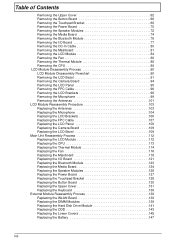
...103 Replacing the Microphone 104 Replacing the LCD Brackets 105 Replacing the FPC Cable 107 Replacing the LCD Panel 108 Replacing the Camera Board 109 Replacing the LCD Bezel 109 Main Unit Reassembly Process 112 Replacing the LCD Module 112 Replacing the CPU 113 Replacing the Thermal Module 114 Replacing the Fan 116 Replacing the Mainboard 118 Replacing the I/O Board 121 Replacing the...
Aspire 5534 Service Guide - Page 9
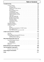
... On Issue 149 No Display Issue 150 Random Loss of BIOS Settings 151 LCD Failure 152 Built-In Keyboard Failure 152 Touchpad Failure 153 Internal Speaker Failure...Check 175 BIOS Recovery by Crisis Disk 176
FRU (Field Replaceable Unit) List
177
Aspire 5534 Exploded Diagrams 178 Main Assembly 178 LCD Assembly 179
Aspire 5534 FRU List 180 Screw List 186
Model Definition and Configuration...
Aspire 5534 Service Guide - Page 14
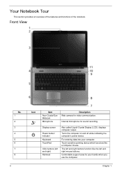
... like the left and right) Palmrest
Also called Liquid-Crystal Display (LCD), displays computer output.
Comfortable support area for your computer.
Turns the computer on and off while indicating the computer's power status. Chapter 1 Front View
No. 1 2 3 4 5 6 7 8
4
Icon
Item
Acer Crystal Eye Webcam
Microphone
Description Web camera for sound recording.
Your Notebook...
Aspire 5534 Service Guide - Page 34

...) X2 Dual Core Processor L310 1200 MHz
WDC WD2500BEVT-22ZCT0 WD-WXE409NM6664 TSSTcorp CDDVDW TS-U633A
v0.14 ATI VGA VER01.022.002.002.033268
Aspire 5534 Acer 65E9A02C-F302-62AB-07B1-00235A9C17AE
F1 Help ESC Exit
Select Item F5/F6 Change Values
F9 Setup Default
Select Menu Enter Select SubMenu F10 Save...
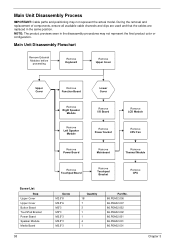
Aspire 5534 Service Guide - Page 68
...Right Speaker
Module
Remove Left Speaker
Module
Remove I/O Board
Remove Power Socket
Remove LCD Module
Remove CPU Fan
Remove Power Board
Remove Mainboard
Remove Thermal Module
Screw List....001
Chapter 3 During the removal and replacement of components, ensure all available cable channels and clips are used and that the cables are replaced in the disassembly procedures may not represent ...
Aspire 5534 Service Guide - Page 100
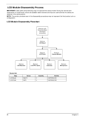
... are used and that the cables are replaced in the disassembly procedures may not represent the actual model. NOTE: The product previews seen in the same position. LCD Module Disassembly Flowchart
Remove LCD Panel from Main
Unit before proceeding
Remove LCD Bezel
Remove LCD Panel
Remove Camera Module
Remove LCD Brackets
Remove LCD FPC Cable
Remove Antennas
Remove Microphone...
Aspire 5534 Service Guide - Page 113
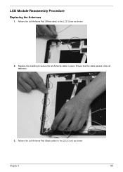
Adhere the Left Antenna Pad (Black cable) to the LCD Cover as shown.
2. Adhere the Left Antenna Pad (White cable) to secure the left Antenna cable in place. Replace the shielding to the LCD Cover as shown. Chapter 3
103
LCD Module Reassembly Procedure
Replacing the Antennas
1. Ensure that the cable passes under all fasteners.
3.
Aspire 5534 Service Guide - Page 114
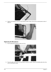
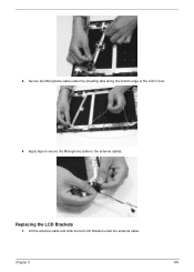
Adhere the shielding tabs where they cover the Microphone cable.
104
Chapter 3
Ensure that the cable passes under all fasteners. Replace the shielding to secure it in place. Push the Microphone Module in place as shown to secure the right Antenna cable in place. Press the cable onto the LCD cover as shown.
2. 4. Replacing the Microphone
1.
Aspire 5534 Service Guide - Page 115
Chapter 3
105 Replacing the LCD Brackets
1. Apply tape to secure the Microphone cable to the antenna cables.
Lift the antenna cable and slide the left LCD Bracket under the shielding tabs along the bottom edge of the LCD Cover. 4.
Secure the Microphone cable under the antenna cable. 3.
Aspire 5534 Service Guide - Page 117

Adhere the clear adhesive tape to the LCD Panel. Replacing the FPC Cable
1. Adhere the camera cable to the LCD Panel.
3. Chapter 3
107
Connect the LCD cable as shown.
2.
Aspire 5534 Service Guide - Page 119
.... Chapter 3
109 Route the LVDS cable through the cable channel and hinge cover as shown.
2.
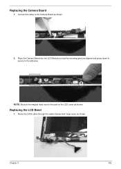
Place the Camera Board into the LCD Module so that the mounting pins are aligned and press down to secure to the post on the LCD cover as shown. Replacing the LCD Bezel
1.
Connect the cable to the Camera Board as shown.
Aspire 5534 Service Guide - Page 122
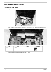
Insert the Microphone cable into the Lower Cover.
2. Step LCD Module
Size M2.5*6
Quantity 3
3. Screw Type
112
Chapter 3
Using both hands, place the LCD Module into the securing clips as shown. Main Unit Reassembly Process
Replacing the LCD Module
1. Replace the three screws on the rear of the Lower Cover to secure the LCD Module to the Lower Cover.
Aspire 5534 Service Guide - Page 160
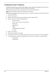
...to correct the problem. 1. Do not replace a non-defective FRUs:
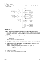
No POST or Video
If the POST or video doesn't display, perform the following occurs:
...display and the external display is still not resolved, see "LCD Failure" on page 191. On this model). Drain any...correctly, add the devices one by removing the power cable and battery and holding down the power button for specific model procedures. ...
Aspire 5534 Service Guide - Page 161
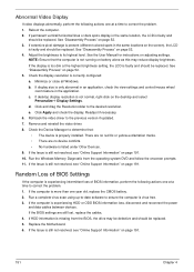
.... 6. Abnormal Video Display
If video displays abnormally, perform the following actions one at the highest brightness setting, the LCD is faulty and should be replaced. NOTE: Ensure that :
• The device is properly installed. Check the display resolution is experiencing HDD or ODD BIOS information loss, disconnect and reconnect the power
and data cables between...
Aspire 5534 Service Guide - Page 175
...non-defective FRU). Visually check them for damage. If the problem remains, replace the following devices:
• Non-Acer devices • Printer, mouse, and other external devices • Battery ... the computer. 5. Power-on page 149): 1. Do not replace a non-defective FRU: • System board • LCD assembly
165
Chapter 4 Undetermined Problems
The diagnostic problems does not...
Aspire 5534 Service Guide - Page 185
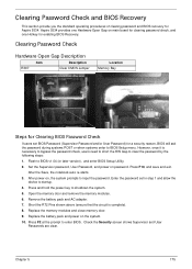
... Press and hold the power key to clear the password by the following steps: 1. Aspire 5534 provides one Hotkey for Clearing BIOS Password Check
If users set in step 1 and allow the
device... the system. 10. Chapter 5
175 After the Save, the notebook auto re-starts. 3. Replace the memory modules and close memory door. 9.
Check the Security screen shows Supervisor and User
Passwords...
Aspire 5534 Service Guide - Page 191
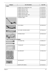
... POWER CORD AUS 3 PIN POWER CORD UK 3 PIN POWER CORD ITALIAN 3 PIN POWER CORD JP 3 PIN IO BOARD CABLE
DC-IN CABLE LCD CABLE, W/CMOS CABLE ANTENNA WLAN
CASE/COVER/BRACKET ASSEMBLY LCD HINGE R&L TP BRACKET
HDD BRACKET
Acer P/N 27.APV02.001 27.TAVV5.001 27.TAVV5.002 27.TAVV5.003 27.TAVV5.004 27.TAVV5.007...
Aspire 5534 Service Guide - Page 194

...ACER EM-7Tv2 HM51 Internal 17 Standard 100KS Black US w/ Canadian French Texture
KB.I170A.128 KB.I170A.134 KB.I170A.138 KB.I170A.139 KB.I170A.140 KB.I170A.142
ASSY LEC LCD MODULE 15.6" WXGA GLARE W/ ANTENNA, CCD 0.3M, ASPIRE
6M.PJU02.002
LCD....007
LCD SCREW RUBBER
47.N6802.001
LCD PANEL MYLAR UPPER CASE MYLAR_B LCD CABLE MYLAR
Mainboard AS5534 ATI RS780 SB710 V1.0 LF, INCL DC-IN CABLE
47....
Aspire 5534 Service Guide - Page 222
... 173 Top View 173
K
Keyboard Removing 60 Replacing 136
Keyboard Failure 152
L
LCD Bezel Removing 91 Replacing 109
LCD Brackets Removing 98 Replacing 105
LCD Cable
Removing 96, 107
LCD Failure 152 LCD Module
Disassembly 90 Reassembly 103 Removing 84 Replacing 112 LCD Module Disassembly Flowchart 90 LCD Panel Removing 95 Replacing 108 Lower Covers Replacing 145
M
Main Unit Disassembly Flowchart 58...
Similar Questions


How To Change Out Lcd Video Cable For Acer Aspire 5534
(Posted by dorjcre 10 years ago)

Need To Replace Lcd Video Cable
Hi, Which is the right part number for LCD video cable for Acer Aspire model S3-3951-6464? Thank ...
Hi, Which is the right part number for LCD video cable for Acer Aspire model S3-3951-6464? Thank ...
(Posted by sergeipersh 10 years ago)

How To Change Out Lcd Video Cable
How to change out LCD Video Cable on ACER Aspire 5534?
How to change out LCD Video Cable on ACER Aspire 5534?
(Posted by iheart81 11 years ago)