eMachines EL1852 Service Guide
Page 75
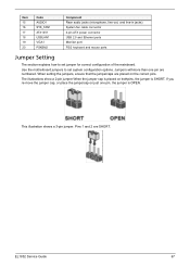
Use the motherboard jumpers to set system configuration options. The illustrations show a 2-pin jumper.When the jumper cap is placed on the correct pins. Jumpers withmore than one ... for correct configuration of the mainboard. This illustration shows a 3-pin jumper. When setting the jumpers, ensure that the jumpercaps are numbered. Pins 1 and 2 are SHORT. EL1852 Service Guide 67
Use the motherboard jumpers to set system configuration options. The illustrations show a 2-pin jumper.When the jumper cap is placed on the correct pins. Jumpers withmore than one ... for correct configuration of the mainboard. This illustration shows a 3-pin jumper. When setting the jumpers, ensure that the jumpercaps are numbered. Pins 1 and 2 are SHORT. EL1852 Service Guide 67
eMachines EL1852 Service Guide
Page 76
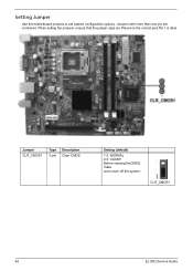
When setting the jumpers, ensure that the jumper caps are numbered. Jumpers with more than one pin are Placed on the correct pins.Pin 1 is label Jumper CLR_CMOS1 Type 3-pin Description Clear CMOS Setting (default) 1-2: NORMAL 2-3: CLEAR Before clearing theCMOS, make sure toturn off the system. CLR_CMOS1 68 EL1852 Service Guide Setting Jumper Use the motherboard jumpers to set system configuration options.
When setting the jumpers, ensure that the jumper caps are numbered. Jumpers with more than one pin are Placed on the correct pins.Pin 1 is label Jumper CLR_CMOS1 Type 3-pin Description Clear CMOS Setting (default) 1-2: NORMAL 2-3: CLEAR Before clearing theCMOS, make sure toturn off the system. CLR_CMOS1 68 EL1852 Service Guide Setting Jumper Use the motherboard jumpers to set system configuration options.
eMachines EL1852 Service Guide
Page 78
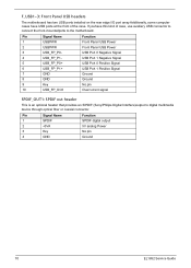
Pin Signal Name 1 SPDIF 2 +5VA 3 Key 4 GND Function SPDIF digital output 5V analog Power No pin Ground 70 EL1852 Service Guide If youhave this kind of the case. Pin Signal Name 1 USBPWR 2 USBPWR 3 USB_FP_P0- 4 USB_FP_P1- 5 USB_FP_P0+ 6 USB_FP_P1+ 7 GND 8 GND 9...: SPDIF out header This is an optional header that provides an S/PDIF (Sony/Philips Digital Interface)output to the motherboard. F_USB1~3: Front Panel USB headers The motherboard has two USB ports installed on the rear edge I/O port array.Additionally, some computer cases have USB ports at ...
Pin Signal Name 1 SPDIF 2 +5VA 3 Key 4 GND Function SPDIF digital output 5V analog Power No pin Ground 70 EL1852 Service Guide If youhave this kind of the case. Pin Signal Name 1 USBPWR 2 USBPWR 3 USB_FP_P0- 4 USB_FP_P1- 5 USB_FP_P0+ 6 USB_FP_P1+ 7 GND 8 GND 9...: SPDIF out header This is an optional header that provides an S/PDIF (Sony/Philips Digital Interface)output to the motherboard. F_USB1~3: Front Panel USB headers The motherboard has two USB ports installed on the rear edge I/O port array.Additionally, some computer cases have USB ports at ...
eMachines EL1852 Service Guide
Page 79
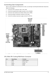
... the following: 1. Refer to SYS_FAN. 5. CPU_FAN: CPU Cooling FAN Power Connector Pin Signal Name 1 GND 2 +12V 3 Sense 4 PWM Function System ground Power +12V Sensor PWM EL1852 Service Guide 71 Connecting Case Components After you have installed the motherboard into a case, you can begin connecting themotherboard components.
... the following: 1. Refer to SYS_FAN. 5. CPU_FAN: CPU Cooling FAN Power Connector Pin Signal Name 1 GND 2 +12V 3 Sense 4 PWM Function System ground Power +12V Sensor PWM EL1852 Service Guide 71 Connecting Case Components After you have installed the motherboard into a case, you can begin connecting themotherboard components.


