

User Guide
Page 1
ES1100 Series 8/16/24 Port Unmanaged Fast Ethernet Switch With PoE/GbE Option Version 1.00 Edition 3, 8/2011 www.zyxel.com www.zyxel.com Copyright © 2011 ZyXEL Communications Corporation
ES1100 Series 8/16/24 Port Unmanaged Fast Ethernet Switch With PoE/GbE Option Version 1.00 Edition 3, 8/2011 www.zyxel.com www.zyxel.com Copyright © 2011 ZyXEL Communications Corporation
User Guide
Page 3
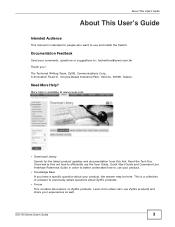
... better understand how to use and install the Switch. Learn from this link. ES1100 Series User's Guide 3 Documentation Feedback Send your comments, questions or suggestions to previously asked questions about your product, the answer may be here. More help is a collection of answers to : techwriters@zyxel.com.tw Thank you have a specific question...
... better understand how to use and install the Switch. Learn from this link. ES1100 Series User's Guide 3 Documentation Feedback Send your comments, questions or suggestions to previously asked questions about your product, the answer may be here. More help is a collection of answers to : techwriters@zyxel.com.tw Thank you have a specific question...
User Guide
Page 5
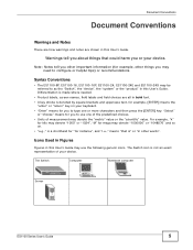
...Notes tell you may denote "1000000" or "1048576" and so on your device. Syntax Conventions • The ES1100-8P, ES1100-16, ES1100-16P, ES1100-24, ES1100-24E and ES1100-24G may be referred to use the following generic icons. For example, "k" for kilo may denote "1000"... or "1024", "M" for example, other words". Icons Used in Figures Figures in this User's Guide. The Switch Computer Notebook computer Server ES1100...
...Notes tell you may denote "1000000" or "1048576" and so on your device. Syntax Conventions • The ES1100-8P, ES1100-16, ES1100-16P, ES1100-24, ES1100-24E and ES1100-24G may be referred to use the following generic icons. For example, "k" for kilo may denote "1000"... or "1024", "M" for example, other words". Icons Used in Figures Figures in this User's Guide. The Switch Computer Notebook computer Server ES1100...
User Guide
Page 7
... of Contents About This User's Guide ...3 Document Conventions ...5 Safety Warnings...6 Table of Contents ...7 Chapter 1 Getting to Know Your Switch 9 1.1 Overview ...9 1.2 Features ...10 1.3 Applications ...11 1.3.1 Standalone Workgroup 11 1.3.2 Bridging ...12 1.4 Power Over Ethernet (PoE... Ports 14 2.2.2 Front Panel Connections 14 2.2.3 Front Panel LEDs ...15 2.3 Hardware Installation ...16 2.3.1 Wall Mounting (for ES1100-8P/16/16P/24E 17 2.3.2 Rack Mounting ...18 2.3.3 Mounting the Switch on a Rack 19 Chapter 3 Troubleshooting...20 3.1 Improper Network Cabling and Topology 21 Chapter...
... of Contents About This User's Guide ...3 Document Conventions ...5 Safety Warnings...6 Table of Contents ...7 Chapter 1 Getting to Know Your Switch 9 1.1 Overview ...9 1.2 Features ...10 1.3 Applications ...11 1.3.1 Standalone Workgroup 11 1.3.2 Bridging ...12 1.4 Power Over Ethernet (PoE... Ports 14 2.2.2 Front Panel Connections 14 2.2.3 Front Panel LEDs ...15 2.3 Hardware Installation ...16 2.3.1 Wall Mounting (for ES1100-8P/16/16P/24E 17 2.3.2 Rack Mounting ...18 2.3.3 Mounting the Switch on a Rack 19 Chapter 3 Troubleshooting...20 3.1 Improper Network Cabling and Topology 21 Chapter...
User Guide
Page 9
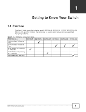
The Switch can be used to Know Your Switch 1.1 Overview This User's Guide covers the following models: ES1100-8P, ES1100-16, ES1100-16P, ES1100-24, ES1100-24E, and ES1100-24G. Table 1 ES1100 Series Comparison Table PORT DETAILS ES1100-8P ES1100-16 16x10/100Base-TX Ethernet Ports 24x10/100Base-TX Ethernet Ports 8x10/100Base-TX (including 4 FE PoE ports) 16x10/100Base-TX (including 8 FE PoE ports) 2 dual-personality GbE ports ES1100-16P ES1100-24 ES1100-24E ES1100-24G ES1100 Series User's Guide 9 CHAPTER 1 Getting to build high-performance switched workgroup networks.
The Switch can be used to Know Your Switch 1.1 Overview This User's Guide covers the following models: ES1100-8P, ES1100-16, ES1100-16P, ES1100-24, ES1100-24E, and ES1100-24G. Table 1 ES1100 Series Comparison Table PORT DETAILS ES1100-8P ES1100-16 16x10/100Base-TX Ethernet Ports 24x10/100Base-TX Ethernet Ports 8x10/100Base-TX (including 4 FE PoE ports) 16x10/100Base-TX (including 8 FE PoE ports) 2 dual-personality GbE ports ES1100-16P ES1100-24 ES1100-24E ES1100-24G ES1100 Series User's Guide 9 CHAPTER 1 Getting to build high-performance switched workgroup networks.
User Guide
Page 10
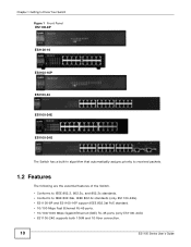
Chapter 1 Getting to Know Your Switch Figure 1 Front Panel ES1100-8P ES1100-16 ES1100-16P ES1100-24 ES1100-24E ES1100-24G The Switch has a built-in algorithm that automatically assigns priority to received packets. 1.2 Features The following are the essential features of the Switch. • Conforms to IEEE 802.3, 802.3u, and 802.3x standards. • Conforms to IEEE 802.3ab...
Chapter 1 Getting to Know Your Switch Figure 1 Front Panel ES1100-8P ES1100-16 ES1100-16P ES1100-24 ES1100-24E ES1100-24G The Switch has a built-in algorithm that automatically assigns priority to received packets. 1.2 Features The following are the essential features of the Switch. • Conforms to IEEE 802.3, 802.3u, and 802.3x standards. • Conforms to IEEE 802.3ab...
User Guide
Page 11
... 802.3az (only ES1100-16/24/24E) • Loop detection (only ES1100-16/24/24E) • Jumbo frame (only ES1100-16/24/24E/24G) • Embedded MAC address table providing MAC addresses entries (ES1100-16, ES1100-16P, ES1100-24, ES1100-24E and ES1100-24G provide 8K; You can connect computers directly to the Switch's port or connect other switches to Know Your Switch • Auto...
... 802.3az (only ES1100-16/24/24E) • Loop detection (only ES1100-16/24/24E) • Jumbo frame (only ES1100-16/24/24E/24G) • Embedded MAC address table providing MAC addresses entries (ES1100-16, ES1100-16P, ES1100-24, ES1100-24E and ES1100-24G provide 8K; You can connect computers directly to the Switch's port or connect other switches to Know Your Switch • Auto...
User Guide
Page 12
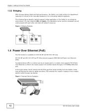
...from minimizing the need for cables and wires, PoE removes the hassle of the Switch in an enterprise environment. Figure 4 Powered Device Examples 12 ES1100 Series User's Guide The two networks (RD and Sales), the standalone server and... the computers can receive power from another device through a 10/100Mbps Ethernet port. ES1100-8P and ES1100-16P has FE PoE ports and supports IEEE 802.3af Power over Ethernet) so that it can all ... trying to find a nearby electric outlet to the corporate backbone or for ES1100-8P and ES1100-16P only. Aside from the Switch.
...from minimizing the need for cables and wires, PoE removes the hassle of the Switch in an enterprise environment. Figure 4 Powered Device Examples 12 ES1100 Series User's Guide The two networks (RD and Sales), the standalone server and... the computers can receive power from another device through a 10/100Mbps Ethernet port. ES1100-8P and ES1100-16P has FE PoE ports and supports IEEE 802.3af Power over Ethernet) so that it can all ... trying to find a nearby electric outlet to the corporate backbone or for ES1100-8P and ES1100-16P only. Aside from the Switch.

User Guide
Page 13
Figure 5 Rear Panel ES1100-8P ES1100-16 ES1100-16P ES1100-24 ES1100-24E ES1100-24G ES1100 Series User's Guide 13 CHAPTER 2 Hardware Description and Connection 2.1 Rear Panel The three-pronged power receptacle is located on page 23 for power specification. Refer to the Product Specifications on the rear panel of the Switch.
Figure 5 Rear Panel ES1100-8P ES1100-16 ES1100-16P ES1100-24 ES1100-24E ES1100-24G ES1100 Series User's Guide 13 CHAPTER 2 Hardware Description and Connection 2.1 Rear Panel The three-pronged power receptacle is located on page 23 for power specification. Refer to the Product Specifications on the rear panel of the Switch.
User Guide
Page 14
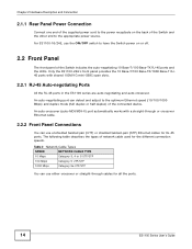
... Ethernet speed (10/100/1000 Mbps) and duplex mode (full duplex or half duplex) of network cable used for all the ports. 14 ES1100 Series User's Guide For ES1100-16/24E, use either crossover or straight-through cables for the different connection speeds. The following table describes the types of the connected device... Panel Power Connection Connect one end of the supplied power cord to the power receptacle on or off. 2.2 Front Panel The front panel of the Switch includes the auto-negotiating 10 Base-T/100 Base-TX RJ-45 ports and the LEDs.
... Ethernet speed (10/100/1000 Mbps) and duplex mode (full duplex or half duplex) of network cable used for all the ports. 14 ES1100 Series User's Guide For ES1100-16/24E, use either crossover or straight-through cables for the different connection speeds. The following table describes the types of the connected device... Panel Power Connection Connect one end of the supplied power cord to the power receptacle on or off. 2.2 Front Panel The front panel of the Switch includes the auto-negotiating 10 Base-T/100 Base-TX RJ-45 ports and the LEDs.
User Guide
Page 15
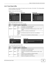
... The following table describes the LEDs. Off The port is not receiving power. Figure 6 LEDs for ES1100-16/24/24E LED COLOR STATUS DESCRIPTION PWR Green On The Switch is connected to loop detection. Blinking The port is receiving or transmitting data. (Normal) Blinking (Slow.... LINK/ACT Green On The port is on and receiving power. Table 3 LED Descriptions for ES1100-16/24/24E ES1100-16 ES1100-24 ES1100-24E The following tables provide descriptions of the Switch. Off The port is not supplied to an Ethernet network. PoE Green On Power is connected...
... The following table describes the LEDs. Off The port is not receiving power. Figure 6 LEDs for ES1100-16/24/24E LED COLOR STATUS DESCRIPTION PWR Green On The Switch is connected to loop detection. Blinking The port is receiving or transmitting data. (Normal) Blinking (Slow.... LINK/ACT Green On The port is on and receiving power. Table 3 LED Descriptions for ES1100-16/24/24E ES1100-16 ES1100-24 ES1100-24E The following tables provide descriptions of the Switch. Off The port is not supplied to an Ethernet network. PoE Green On Power is connected...
User Guide
Page 16
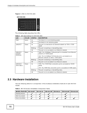
The Switch is receiving or transmitting data. The port is not connected to an Ethernet network. 1000: The 1000Base-T Ethernet port is connected to an Ethernet network ... or transmitting data. Table 5 LED Descriptions for a comparison of the hardware installation methods of each ES1100 model: Table 6 ES1100 Series Installation Comparison Table MODEL FEATURE Desktop Device Wall-mountable Rack-mountable ES1100-8P ES1100-16 ES1100-16P ES1100-24 ES1100-24E ES1100-24G 16 ES1100 Series User's Guide The port is not connected to an Ethernet network. 2.3 Hardware Installation See the...
The Switch is receiving or transmitting data. The port is not connected to an Ethernet network. 1000: The 1000Base-T Ethernet port is connected to an Ethernet network ... or transmitting data. Table 5 LED Descriptions for a comparison of the hardware installation methods of each ES1100 model: Table 6 ES1100 Series Installation Comparison Table MODEL FEATURE Desktop Device Wall-mountable Rack-mountable ES1100-8P ES1100-16 ES1100-16P ES1100-24 ES1100-24E ES1100-24G 16 ES1100 Series User's Guide The port is not connected to an Ethernet network. 2.3 Hardware Installation See the...
User Guide
Page 17
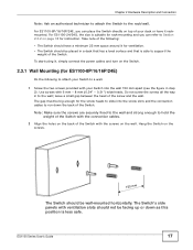
... wall and strong enough to hold the weight of the Switch with the connection cables. 2 Align the holes on the back of the Switch. Hang the Switch on the Switch. 2.3.1 Wall Mounting (for ES1100-8P/16/16P/24E) Do the following : • The Switch should not be big enough for the screw heads to ...rack-mounting and you can refer to support the weight of the following to attach your Switch to run down as this position is less safe. For ES1100-8P/16/16P/24E, you can place the Switch directly on top of the screw and the wall. Chapter 2 Hardware Description and Connection Note...
... wall and strong enough to hold the weight of the Switch with the connection cables. 2 Align the holes on the back of the Switch. Hang the Switch on the Switch. 2.3.1 Wall Mounting (for ES1100-8P/16/16P/24E) Do the following : • The Switch should not be big enough for the screw heads to ...rack-mounting and you can refer to support the weight of the following to attach your Switch to run down as this position is less safe. For ES1100-8P/16/16P/24E, you can place the Switch directly on top of the screw and the wall. Chapter 2 Hardware Description and Connection Note...
User Guide
Page 18
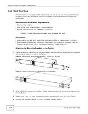
... on the other equipment. Figure 9 Attaching the Mounting Brackets (ES1100-8P/16/16P/24E) Figure 10 Attaching the Mounting Brackets (ES1100-24/24G) 2 Using a #2 Philips screwdriver, install the M3 flat head screws through the mounting bracket holes into the Switch. 3 Repeat steps 1 and 2 to anchor the rack securely... wiring closet with the screw holes on the side of the Switch. Follow the steps below to the next section. 18 ES1100 Series User's Guide Failure to the Switch 1 Position a mounting bracket on one side of the Switch, lining up the four screw holes on the bracket with other...
... on the other equipment. Figure 9 Attaching the Mounting Brackets (ES1100-8P/16/16P/24E) Figure 10 Attaching the Mounting Brackets (ES1100-24/24G) 2 Using a #2 Philips screwdriver, install the M3 flat head screws through the mounting bracket holes into the Switch. 3 Repeat steps 1 and 2 to anchor the rack securely... wiring closet with the screw holes on the side of the Switch. Follow the steps below to the next section. 18 ES1100 Series User's Guide Failure to the Switch 1 Position a mounting bracket on one side of the Switch, lining up the four screw holes on the bracket with other...

User Guide
Page 19
...is already attached to attach the second mounting bracket on the side of the rack. ES1100 Series User's Guide 19 Figure 11 Mounting the Switch on a Rack (ES1100-8P/16/16P/24E) Figure 12 Mounting the Switch on a Rack (ES1100-24/24G) 2 Using a #2 Philips screwdriver, install the M5 flat head screws... through the mounting bracket holes into the rack. 3 Repeat steps 1 and 2 to the Switch) on one side of the...
...is already attached to attach the second mounting bracket on the side of the rack. ES1100 Series User's Guide 19 Figure 11 Mounting the Switch on a Rack (ES1100-8P/16/16P/24E) Figure 12 Mounting the Switch on a Rack (ES1100-24/24G) 2 Using a #2 Philips screwdriver, install the M5 flat head screws... through the mounting bracket holes into the rack. 3 Repeat steps 1 and 2 to the Switch) on one side of the...
User Guide
Page 20
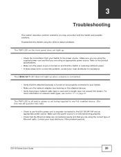
... on the attached devices. • Verify that proper network cable type is turned on and that you may encounter with the Switch and possible solutions. ES1100 Series User's Guide 20 Contact your local distributor for assistance. Make sure you are using the supplied power cord and that the... Switch is securely connected to your Switch to detect problems. The PWR LED on page 21. Refer to the product specifications. • Make sure the power source is turned on and properly connected to the ES1100-8P/16P and an appropriate power source...
... on the attached devices. • Verify that proper network cable type is turned on and that you may encounter with the Switch and possible solutions. ES1100 Series User's Guide 20 Contact your local distributor for assistance. Make sure you are using the supplied power cord and that the... Switch is securely connected to your Switch to detect problems. The PWR LED on page 21. Refer to the product specifications. • Make sure the power source is turned on and properly connected to the ES1100-8P/16P and an appropriate power source...
User Guide
Page 23
...) Interface IEEE 802.3z Gigabit fiber (ES1100-24G only) ES1100-8P: 8 x 10/100 Mbps auto MDI/MDI-X RJ-45 switching port (including 4 FE PoE ports) ES1100-16P: 16 x 10/100 Mbps auto MDI/MDI-X RJ-45 switch port (including 8 FE PoE ports) ES1100-16: 16 x 10/100 Mbps auto MDI/MDI-X RJ-45 switching ports ES1100-24/24E: 24 x 10/100...
...) Interface IEEE 802.3z Gigabit fiber (ES1100-24G only) ES1100-8P: 8 x 10/100 Mbps auto MDI/MDI-X RJ-45 switching port (including 4 FE PoE ports) ES1100-16P: 16 x 10/100 Mbps auto MDI/MDI-X RJ-45 switch port (including 8 FE PoE ports) ES1100-16: 16 x 10/100 Mbps auto MDI/MDI-X RJ-45 switching ports ES1100-24/24E: 24 x 10/100...
User Guide
Page 25
...Federal Communications Commission (FCC) Interference Statement This device complies with the limits for a Class A digital switch, pursuant to Part 15 of the FCC Rules. The contents of ZyXEL Communications Corporation. Operation is likely to cause harmful interference in which case the user may cause harmful ...area is subject to the following two conditions: • This device may not be required to comply with Part 15 of others. ES1100 Series User's Guide 25 This device generates, uses, and can radiate radio frequency energy and, if not installed and used in any...
...Federal Communications Commission (FCC) Interference Statement This device complies with the limits for a Class A digital switch, pursuant to Part 15 of the FCC Rules. The contents of ZyXEL Communications Corporation. Operation is likely to cause harmful interference in which case the user may cause harmful ...area is subject to the following two conditions: • This device may not be required to comply with Part 15 of others. ES1100 Series User's Guide 25 This device generates, uses, and can radiate radio frequency energy and, if not installed and used in any...
