
User Guide
Page 7
... Panel ...14 2.2.1 RJ-45 Auto-negotiating Ports 14 2.2.2 Front Panel Connections 14 2.2.3 Front Panel LEDs ...15 2.3 Hardware Installation ...16 2.3.1 Wall Mounting (for ES1100-8P/16/16P/24E 17 2.3.2 Rack Mounting ...18 2.3.3 Mounting the Switch on a Rack 19 Chapter 3 Troubleshooting...20 3.1 Improper Network Cabling and Topology 21 Chapter 4 Product Specifications ...23 Appendix A Legal Information 25 Index...
... Panel ...14 2.2.1 RJ-45 Auto-negotiating Ports 14 2.2.2 Front Panel Connections 14 2.2.3 Front Panel LEDs ...15 2.3 Hardware Installation ...16 2.3.1 Wall Mounting (for ES1100-8P/16/16P/24E 17 2.3.2 Rack Mounting ...18 2.3.3 Mounting the Switch on a Rack 19 Chapter 3 Troubleshooting...20 3.1 Improper Network Cabling and Topology 21 Chapter 4 Product Specifications ...23 Appendix A Legal Information 25 Index...
User Guide
Page 16
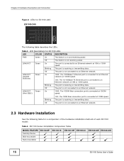
...LED Descriptions for a comparison of the hardware installation methods of each ES1100 model: Table 6 ES1100 Series Installation Comparison Table MODEL FEATURE Desktop Device Wall-mountable Rack-mountable ES1100-8P ES1100-16 ES1100-16P ES1100-24 ES1100-24E ES1100-24G 16 ES1100 Series User's Guide The port is not receiving power. The ...The port is receiving or transmitting data. Chapter 2 Hardware Description and Connection Figure 8 LEDs for ES1100-24G ES1100-24G The following table for ES1100-24G LED PWR LINK/ACT LINK/ACT (Gigabit Ethernet) LINK/ACT (Mini-GBIC) COLOR Green Green...
...LED Descriptions for a comparison of the hardware installation methods of each ES1100 model: Table 6 ES1100 Series Installation Comparison Table MODEL FEATURE Desktop Device Wall-mountable Rack-mountable ES1100-8P ES1100-16 ES1100-16P ES1100-24 ES1100-24E ES1100-24G 16 ES1100 Series User's Guide The port is not receiving power. The ...The port is receiving or transmitting data. Chapter 2 Hardware Description and Connection Figure 8 LEDs for ES1100-24G ES1100-24G The following table for ES1100-24G LED PWR LINK/ACT LINK/ACT (Gigabit Ethernet) LINK/ACT (Mini-GBIC) COLOR Green Green...
User Guide
Page 17
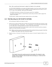
...: Make sure the screws are securely fixed to the wall and strong enough to the wall; Hang the Switch on the Switch. 2.3.1 Wall Mounting (for ES1100-8P/16/16P/24E) Do the following : • The Switch should have it , simply connect the power cables and turn on the screws. 150 mm The... is able to the rack/wall. The Switch's side panels with 6 mm ~ 8 mm (0.24" ~ 0.31") wide heads. leave a small gap between the head of your Switch into the wall 150 mm apart (see the figure in a desk that has a level surface and that is less safe. For ES1100-8P/16/16P/24E, you...
...: Make sure the screws are securely fixed to the wall and strong enough to the wall; Hang the Switch on the Switch. 2.3.1 Wall Mounting (for ES1100-8P/16/16P/24E) Do the following : • The Switch should have it , simply connect the power cables and turn on the screws. 150 mm The... is able to the rack/wall. The Switch's side panels with 6 mm ~ 8 mm (0.24" ~ 0.31") wide heads. leave a small gap between the head of your Switch into the wall 150 mm apart (see the figure in a desk that has a level surface and that is less safe. For ES1100-8P/16/16P/24E, you...
User Guide
Page 18
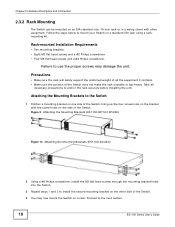
... in a wiring closet with the screw holes on a standard EIA rack using a rackmounting kit. Failure to install the second mounting bracket on a rack. Figure 9 Attaching the Mounting Brackets (ES1100-8P/16/16P/24E) Figure 10 Attaching the Mounting Brackets (ES1100-24/24G) 2 Using a #2 Philips screwdriver, install the M3 flat head screws through the mounting bracket...
... in a wiring closet with the screw holes on a standard EIA rack using a rackmounting kit. Failure to install the second mounting bracket on a rack. Figure 9 Attaching the Mounting Brackets (ES1100-8P/16/16P/24E) Figure 10 Attaching the Mounting Brackets (ES1100-24/24G) 2 Using a #2 Philips screwdriver, install the M3 flat head screws through the mounting bracket...

User Guide
Page 19
... Figure 11 Mounting the Switch on a Rack (ES1100-8P/16/16P/24E) Figure 12 Mounting the Switch on a Rack (ES1100-24/24G) 2 Using a #2 Philips screwdriver, install the M5 flat head screws through the mounting bracket holes into the rack. 3 Repeat steps 1 and 2 to the Switch) on one side of the rack, lining up the two screw holes...
... Figure 11 Mounting the Switch on a Rack (ES1100-8P/16/16P/24E) Figure 12 Mounting the Switch on a Rack (ES1100-24/24G) 2 Using a #2 Philips screwdriver, install the M5 flat head screws through the mounting bracket holes into the rack. 3 Repeat steps 1 and 2 to the Switch) on one side of the rack, lining up the two screw holes...
User Guide
Page 27
... cables 21 FCC interference statement 25 Front Panel 14 Front Panel Connections 14 I installation precautions 18 ES1100 Series User's Guide Index Index L LED Descriptions LK/ACT 15, 16 PWR 15, 16 M mounting brackets 18 N network cable crossover 14 straight-through 14 Network Cable Types 14 Non-...standard network cables 21 P product registration 26 Product specification 23 R rack mounting 18 Rear Panel 13 Rear Panel Power Connection ...
... cables 21 FCC interference statement 25 Front Panel 14 Front Panel Connections 14 I installation precautions 18 ES1100 Series User's Guide Index Index L LED Descriptions LK/ACT 15, 16 PWR 15, 16 M mounting brackets 18 N network cable crossover 14 straight-through 14 Network Cable Types 14 Non-...standard network cables 21 P product registration 26 Product specification 23 R rack mounting 18 Rear Panel 13 Rear Panel Power Connection ...