Owner's Manual
Page 3
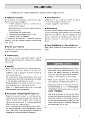
...disassemble it, taking care to pack each component properly. PRECAUTIONS Please read the following locations may cause damage to the tone bars and frame parts or topple the instrument, which is disconnected and the caster brakes are in Use • Make sure to turn off using a soft and... the controller or driver, as this manual. Be- q When Not in the opposite order of the striking surface (YV3910/3710/3700: P. 18, YV-2700/2700G/ 1600A/520: P 25) should be wiped off the power switch and discon- Use of different adapters may cause the instrument to shift during performance ...
...disassemble it, taking care to pack each component properly. PRECAUTIONS Please read the following locations may cause damage to the tone bars and frame parts or topple the instrument, which is disconnected and the caster brakes are in Use • Make sure to turn off using a soft and... the controller or driver, as this manual. Be- q When Not in the opposite order of the striking surface (YV3910/3710/3700: P. 18, YV-2700/2700G/ 1600A/520: P 25) should be wiped off the power switch and discon- Use of different adapters may cause the instrument to shift during performance ...
Owner's Manual
Page 22
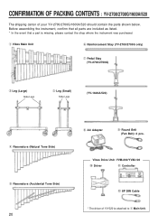
... !1 Controller !2 8P DIN Cable * The driver of your YV-2700/2700G/1600A/520 should contain the parts shown below. Before assembling the instrument, confirm that all parts are included as listed. * In the event that a part is attached to q Main Unit. q Vibes Main Unit y Reinforcement Stay (YV-2700/2700G only) u Pedal Stay (YV-2700/2700G) w Leg (Large) Slide Legs e Leg (Small) Slide...
... !1 Controller !2 8P DIN Cable * The driver of your YV-2700/2700G/1600A/520 should contain the parts shown below. Before assembling the instrument, confirm that all parts are included as listed. * In the event that a part is attached to q Main Unit. q Vibes Main Unit y Reinforcement Stay (YV-2700/2700G only) u Pedal Stay (YV-2700/2700G) w Leg (Large) Slide Legs e Leg (Small) Slide...
Owner's Manual
Page 24
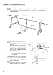
... the reinforcement stay. tion position. 6 In the same way, insert the reinforce- ASSEMBLY : YV-2700/2700G/1600A/520 4 Place the large leg, small leg, pedal stay and reinforcement stay* so that after assembly each part will be positioned as illustrated. (* YV-1600A/520 is not equipped with a reinforcement stay) Low Sound Side Leg (Large) Reinforcement...
... the reinforcement stay. tion position. 6 In the same way, insert the reinforce- ASSEMBLY : YV-2700/2700G/1600A/520 4 Place the large leg, small leg, pedal stay and reinforcement stay* so that after assembly each part will be positioned as illustrated. (* YV-1600A/520 is not equipped with a reinforcement stay) Low Sound Side Leg (Large) Reinforcement...
Owner's Manual
Page 25
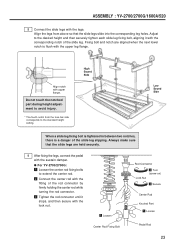
... When a slide leg fixing bolt is tightened in between two notches, there is flush with the corresponding notch of the slide leg. q For YV-2700/2700G: z Loosen the center rod fixing bolts to the standard height setting. Always make sure that the slide legs slide into the corresponding leg holes.... x Connect the center rod with upper flange. z Loosen Center Rod Fixing Bolt Rod Connector x Turn (screw on) Lock Nut c Secure Center Rod Knurled Part z Loosen Pedal Rod 23 Fixing bolt and notch are held securely. 9 After fixing the legs, connect the pedal with the legs. c Tighten the rod ...
... When a slide leg fixing bolt is tightened in between two notches, there is flush with the corresponding notch of the slide leg. q For YV-2700/2700G: z Loosen the center rod fixing bolts to the standard height setting. Always make sure that the slide legs slide into the corresponding leg holes.... x Connect the center rod with upper flange. z Loosen Center Rod Fixing Bolt Rod Connector x Turn (screw on) Lock Nut c Secure Center Rod Knurled Part z Loosen Pedal Rod 23 Fixing bolt and notch are held securely. 9 After fixing the legs, connect the pedal with the legs. c Tighten the rod ...
Owner's Manual
Page 26
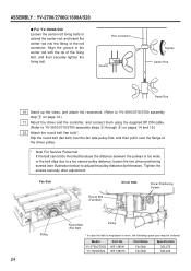
... connector. Tighten the screws securely after adjustment. W5 128041 W5 128070 Part Name Fan Belt Fan Belt Specification 3ØL275 3ØL236 24 ASSEMBLY : YV-2700/2700G/1600A/520 q For YV-1600A/520 Loosen the center rod fixing bolts to YV-3910/3710/3700 assembly steps n through , on pages 14 and ...Service Personnel If the belt cannot be mounted because the distance between the pulleys is misplaced or worn, the following spare part may be ordered: Model YV-2700/2700G YV-1600A/520 Part No. Slip the round belt (fan belt) over the fan side pulley first, and then pull it over the...
... connector. Tighten the screws securely after adjustment. W5 128041 W5 128070 Part Name Fan Belt Fan Belt Specification 3ØL275 3ØL236 24 ASSEMBLY : YV-2700/2700G/1600A/520 q For YV-1600A/520 Loosen the center rod fixing bolts to YV-3910/3710/3700 assembly steps n through , on pages 14 and ...Service Personnel If the belt cannot be mounted because the distance between the pulleys is misplaced or worn, the following spare part may be ordered: Model YV-2700/2700G YV-1600A/520 Part No. Slip the round belt (fan belt) over the fan side pulley first, and then pull it over the...
Owner's Manual
Page 27
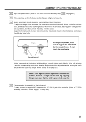
...instrument by hand (do not touch the metal parts shown in between two notches, there is tightened securely. 15 Height adjustment should always be performed by at least 2 persons. ASSEMBLY : YV-2700/2700G/1600A/520 13 Adjust the pedal stroke. (Refer to YV-3910/3710/3700 assembly step 10-1 on page... 17.) 14 After assembly, confirm that the slide legs are aligned when the next higher notch is flush with the corresponding notch of the controller. (Refer to YV-3700 assembly...
...instrument by hand (do not touch the metal parts shown in between two notches, there is tightened securely. 15 Height adjustment should always be performed by at least 2 persons. ASSEMBLY : YV-2700/2700G/1600A/520 13 Adjust the pedal stroke. (Refer to YV-3910/3710/3700 assembly step 10-1 on page... 17.) 14 After assembly, confirm that the slide legs are aligned when the next higher notch is flush with the corresponding notch of the controller. (Refer to YV-3700 assembly...

