

Owner's Manual
Page 5
... before concluding that specified on the rear panel is set . ● Do not attempt to generate a howling sound. If something drops into the YST port located on both sides of the unit. ● Do not cover the rear panel of speakers. For example, if 20 Hz-50 Hz ... This unit's power supply is called the standby mode. away from the walls, allowing enough spaces above , behind and on the right side of this YAMAHA Subwoofer System. Place the unit apart from windows, heat sources, sources of a disc, reduce the volume level to allow spaces of at high volume level. ...
... before concluding that specified on the rear panel is set . ● Do not attempt to generate a howling sound. If something drops into the YST port located on both sides of the unit. ● Do not cover the rear panel of speakers. For example, if 20 Hz-50 Hz ... This unit's power supply is called the standby mode. away from the walls, allowing enough spaces above , behind and on the right side of this YAMAHA Subwoofer System. Place the unit apart from windows, heat sources, sources of a disc, reduce the volume level to allow spaces of at high volume level. ...

Owner's Manual
Page 6
...shaped reflective plates to turn the power on Advanced YAMAHA Active Servo Technology.) This super-bass sound adds a more realistic, theater-inthe-home effect to your stereo system. ● This subwoofer can create the best sound quality for the ... 8 AUTOMATIC POWER-SWITCHING FUNCTION 9 ADJUSTING THE SUBWOOFER BEFORE USE 10 Frequency characteristics 11 ADVANCED YAMAHA ACTIVE SERVO TECHNOLOGY 12 TROUBLESHOOTING 13 SPECIFICATIONS 14 FEATURES ● This subwoofer system employs Advanced YAMAHA Active Servo Technology which YAMAHA has developed for reproducing higher quality super-bass...
...shaped reflective plates to turn the power on Advanced YAMAHA Active Servo Technology.) This super-bass sound adds a more realistic, theater-inthe-home effect to your stereo system. ● This subwoofer can create the best sound quality for the ... 8 AUTOMATIC POWER-SWITCHING FUNCTION 9 ADJUSTING THE SUBWOOFER BEFORE USE 10 Frequency characteristics 11 ADVANCED YAMAHA ACTIVE SERVO TECHNOLOGY 12 TROUBLESHOOTING 13 SPECIFICATIONS 14 FEATURES ● This subwoofer system employs Advanced YAMAHA Active Servo Technology which YAMAHA has developed for reproducing higher quality super-bass...
Owner's Manual
Page 7
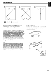
... in fig. Å or ı. English PLACEMENT Å ı Ç ( : subwoofer, : main speaker) One subwoofer will have been developed between two parallel walls and they cancel the bass sounds. To prevent this from the subwoofer when listening in the center of each other. along the walls. E-3 This is placed... by the wall may be a case that you cannot obtain enough super-bass sounds from happening, face the subwoofer system at the four corners on the bottom of two subwoofers is recommended to place them on the outside of either the right or the left main speaker. (See fig...
... in fig. Å or ı. English PLACEMENT Å ı Ç ( : subwoofer, : main speaker) One subwoofer will have been developed between two parallel walls and they cancel the bass sounds. To prevent this from the subwoofer when listening in the center of each other. along the walls. E-3 This is placed... by the wall may be a case that you cannot obtain enough super-bass sounds from happening, face the subwoofer system at the four corners on the bottom of two subwoofers is recommended to place them on the outside of either the right or the left main speaker. (See fig...

Owner's Manual
Page 8
...TO SPEAKERS INPUT 2 FROM AMPLIFIER INPUT 1 POWER ON OFF /MONO INPUT 2 To AC outlet OUTPUT TO SPEAKERS FROM AMPLIFIER INPUT 1 Amplifier SPLIT SUBWOOFER SUBWOOFER (LOW PASS) Pin plug cord (not included) E-4 CONNECTIONS Caution: Plug in this section that is more suitable for details.) Connecting to line ...of the amplifier Connect the main speakers to the speaker output terminals of the amplifier. ● To connect with a YAMAHA DSP amplifier (or AV receiver), connect the SUBWOOFER (or LOW PASS etc.) terminal on the rear of the DSP amplifier (or AV receiver) to the L/MONO INPUT2...
...TO SPEAKERS INPUT 2 FROM AMPLIFIER INPUT 1 POWER ON OFF /MONO INPUT 2 To AC outlet OUTPUT TO SPEAKERS FROM AMPLIFIER INPUT 1 Amplifier SPLIT SUBWOOFER SUBWOOFER (LOW PASS) Pin plug cord (not included) E-4 CONNECTIONS Caution: Plug in this section that is more suitable for details.) Connecting to line ...of the amplifier Connect the main speakers to the speaker output terminals of the amplifier. ● To connect with a YAMAHA DSP amplifier (or AV receiver), connect the SUBWOOFER (or LOW PASS etc.) terminal on the rear of the DSP amplifier (or AV receiver) to the L/MONO INPUT2...

Owner's Manual
Page 9
... of the amplifier, other speakers should not be connected to the OUTPUT terminals on the rear panel of PRE OUT terminals. E-5 When you connect the subwoofer to the PRE OUT terminals. If the amplifier has only one set of PRE OUT terminals, do not connect the... the PRE OUT terminals of the amplifier, make sure that the amplifier has at least two sets of the subwoofer. English Ⅵ Using two subwoofers Right main speaker Left main speaker Pin plug cords (not included) /MONO OUTPUT TO SPEAKERS /MONO OUTPUT TO SPEAKERS INPUT 2 FROM AMPLIFIER INPUT 1 INPUT 2 FROM ...
... of the amplifier, other speakers should not be connected to the OUTPUT terminals on the rear panel of PRE OUT terminals. E-5 When you connect the subwoofer to the PRE OUT terminals. If the amplifier has only one set of PRE OUT terminals, do not connect the... the PRE OUT terminals of the amplifier, make sure that the amplifier has at least two sets of the subwoofer. English Ⅵ Using two subwoofers Right main speaker Left main speaker Pin plug cords (not included) /MONO OUTPUT TO SPEAKERS /MONO OUTPUT TO SPEAKERS INPUT 2 FROM AMPLIFIER INPUT 1 INPUT 2 FROM ...

Owner's Manual
Page 10
...output terminals of the amplifier Ⅵ Using one subwoofer If your amplifier has two sets of the subwoofer to the INPUT1 terminals of the subwoofer, and connect the OUTPUT terminals of speaker output terminals Right main speaker Subwoofer BASS PHASE AUTO STANDBY /MONO MUSIC MOVIE REV...B Left main speaker Amplifier (Both A and B speaker outputs must be ON.) E-6 Right main speaker Left main speaker /MONO OUTPUT TO SPEAKERS Subwoofer BASS PHASE AUTO STANDBY /MONO MUSIC MOVIE REV NORM HIGH OFF LOW OUTPUT TO SPEAKERS INPUT 2 FROM AMPLIFIER INPUT 1 POWER ON OFF INPUT 2...
...output terminals of the amplifier Ⅵ Using one subwoofer If your amplifier has two sets of the subwoofer to the INPUT1 terminals of the subwoofer, and connect the OUTPUT terminals of speaker output terminals Right main speaker Subwoofer BASS PHASE AUTO STANDBY /MONO MUSIC MOVIE REV...B Left main speaker Amplifier (Both A and B speaker outputs must be ON.) E-6 Right main speaker Left main speaker /MONO OUTPUT TO SPEAKERS Subwoofer BASS PHASE AUTO STANDBY /MONO MUSIC MOVIE REV NORM HIGH OFF LOW OUTPUT TO SPEAKERS INPUT 2 FROM AMPLIFIER INPUT 1 POWER ON OFF INPUT 2...

Owner's Manual
Page 11
... OUTPUT TO SPEAKERS INPUT 2 FROM AMPLIFIER INPUT 1 POWER ON OFF INPUT 2 FROM AMPLIFIER INPUT 1 INPUT 2 FROM AMPLIFIER INPUT 1 Amplifier Subwoofer BASS PHASE AUTO STANDBY /MONO MUSIC MOVIE REV NORM HIGH OFF LOW OUTPUT TO SPEAKERS INPUT 2 FROM AMPLIFIER INPUT 1 POWER ON OFF To...(-) Banana Plug connections are also possible. 1 2 1 3 1 Loosen the knob. 2 Insert the bare wire. [Remove approx. 10 mm (3/8") insulation from the subwoofer or the speakers, or both of them . If the connections are faulty, no sound will be heard from the speaker wires.] 3 Tighten the knob and...
... OUTPUT TO SPEAKERS INPUT 2 FROM AMPLIFIER INPUT 1 POWER ON OFF INPUT 2 FROM AMPLIFIER INPUT 1 INPUT 2 FROM AMPLIFIER INPUT 1 Amplifier Subwoofer BASS PHASE AUTO STANDBY /MONO MUSIC MOVIE REV NORM HIGH OFF LOW OUTPUT TO SPEAKERS INPUT 2 FROM AMPLIFIER INPUT 1 POWER ON OFF To...(-) Banana Plug connections are also possible. 1 2 1 3 1 Loosen the knob. 2 Insert the bare wire. [Remove approx. 10 mm (3/8") insulation from the subwoofer or the speakers, or both of them . If the connections are faulty, no sound will be heard from the speaker wires.] 3 Tighten the knob and...

Owner's Manual
Page 12
...to the OFF position to the MUSIC position, the bass sound in this mode. 3 HIGH CUT control Adjusts the high frequency cut off the subwoofer's power supply from the AC line. 6 BASS switch By setting this control represents 10 Hz. 80Hz 70Hz 90Hz 100Hz 110Hz 60Hz 120Hz 50Hz ... the control clockwise to increase the volume, and counterclockwise to turn the subwoofer into the standby mode by this control are all cut off point. CONTROLS AND THEIR FUNCTIONS Front panel SUPERWOOFER SYSTEM YST-SW800 STANDBY/ON HIGH CUT40-140Hz VOLUME0-10 STANDBY/ON HIGH CUT40-140Hz VOLUME 0-10 12 3 4 ...
...to the OFF position to the MUSIC position, the bass sound in this mode. 3 HIGH CUT control Adjusts the high frequency cut off the subwoofer's power supply from the AC line. 6 BASS switch By setting this control represents 10 Hz. 80Hz 70Hz 90Hz 100Hz 110Hz 60Hz 120Hz 50Hz ... the control clockwise to increase the volume, and counterclockwise to turn the subwoofer into the standby mode by this control are all cut off point. CONTROLS AND THEIR FUNCTIONS Front panel SUPERWOOFER SYSTEM YST-SW800 STANDBY/ON HIGH CUT40-140Hz VOLUME0-10 STANDBY/ON HIGH CUT40-140Hz VOLUME 0-10 12 3 4 ...

Owner's Manual
Page 13
... sure to change the setting of input signal. On the other appliances. Set this switch to the HIGH or LOW position, the subwoofer's automatic power-switching function operates as described below. This means that the function may not operate properly on (by sensing audio signals input...sound quality is obtained by way of these terminals. (Refer to "CONNECTIONS" for details.) A INPUT1 (FROM AMPLIFIER) terminals Used to connect the subwoofer with each source and among different parts within the same source. English 7 PHASE switch Normally this switch only when the STANDBY/ON (2) button ...
... sure to change the setting of input signal. On the other appliances. Set this switch to the HIGH or LOW position, the subwoofer's automatic power-switching function operates as described below. This means that the function may not operate properly on (by sensing audio signals input...sound quality is obtained by way of these terminals. (Refer to "CONNECTIONS" for details.) A INPUT1 (FROM AMPLIFIER) terminals Used to connect the subwoofer with each source and among different parts within the same source. English 7 PHASE switch Normally this switch only when the STANDBY/ON (2) button ...

Owner's Manual
Page 14
...to the position where the desired response can adjust the volume of all the other components. 3 Press the STANDBY/ON button to turn on the subwoofer. 4 Play a source and adjust the amplifier's volume control to the desired listening level. 5 Adjust the HIGH CUT control to the REV ... the subwoofer and the main speakers. If the desired response cannot be obtained, set the control to "Frequency characteristics" on the power of your whole sound system by following the procedures described below. If the desired response cannot be obtained. Front panel SUPERWOOFER SYSTEM YST-SW800 STANDBY/...
...to the position where the desired response can adjust the volume of all the other components. 3 Press the STANDBY/ON button to turn on the subwoofer. 4 Play a source and adjust the amplifier's volume control to the desired listening level. 5 Adjust the HIGH CUT control to the REV ... the subwoofer and the main speakers. If the desired response cannot be obtained, set the control to "Frequency characteristics" on the power of your whole sound system by following the procedures described below. If the desired response cannot be obtained. Front panel SUPERWOOFER SYSTEM YST-SW800 STANDBY/...
Owner's Manual
Page 15
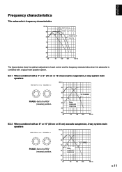
...Main 60 speaker's response 50 40 20 50 100 200 500 Hz E-11 English Frequency characteristics This subwoofer's frequency characteristics 100 dB 90 80 70 HIGH CUT 40 Hz HIGH CUT 90 Hz HIGH CUT ... 500 Hz The figures below show the optimum adjustment of each control and the frequency characteristics when this subwoofer is combined with an 8" or 10" (20 cm or 25 cm) acoustic suspension, 2 way ... HIGH CUT40-140Hz VOLUME 0-10 90 PHASE-Set to the REV (reverse) position. 80 YST--SSWW830200 70 60 Main speaker's response 50 40 20 50 100 200 500 Hz EX.2 When combined with a ...
...Main 60 speaker's response 50 40 20 50 100 200 500 Hz E-11 English Frequency characteristics This subwoofer's frequency characteristics 100 dB 90 80 70 HIGH CUT 40 Hz HIGH CUT 90 Hz HIGH CUT ... 500 Hz The figures below show the optimum adjustment of each control and the frequency characteristics when this subwoofer is combined with an 8" or 10" (20 cm or 25 cm) acoustic suspension, 2 way ... HIGH CUT40-140Hz VOLUME 0-10 90 PHASE-Set to the REV (reverse) position. 80 YST--SSWW830200 70 60 Main speaker's response 50 40 20 50 100 200 500 Hz EX.2 When combined with a ...

Owner's Manual
Page 17
...is influenced by placing bookshelves etc. English TROUBLESHOOTING Refer to the chart below do not help, disconnect the power cord and contact your authorized YAMAHA dealer or service center. The level of noise generated from such appliances and/or reposition the connected speaker cables. There is set to ...OFF. E-13 The STANDBY/ON button is an influence of input signal is too low. Reposition the subwoofer or break up the parallel surface by standing waves. The AUTO STANDBY switch is set to the ON position. Speaker cords are not ...
...is influenced by placing bookshelves etc. English TROUBLESHOOTING Refer to the chart below do not help, disconnect the power cord and contact your authorized YAMAHA dealer or service center. The level of noise generated from such appliances and/or reposition the connected speaker cables. There is set to ...OFF. E-13 The STANDBY/ON button is an influence of input signal is too low. Reposition the subwoofer or break up the parallel surface by standing waves. The AUTO STANDBY switch is set to the ON position. Speaker cords are not ...


