
Owners Manual
Page 4
...foreign objects such as water drips might cause personal injury and/or damage to this unit. • Never place a fragile object near the YST port of a disc, reduce the volume level to prevent this unit from being damaged. • If you hear distorted noise (i.e., unnatural, ... not cover the rear panel of humming (transformers, motors). Place the unit apart from electronic instruments, etc. Furthermore, do not expose this YAMAHA subwoofer system. CAUTION: Read this speaker system. • Vibration generated by vibrations, it may cause bodily injury. For example, if 20 Hz-50...
...foreign objects such as water drips might cause personal injury and/or damage to this unit. • Never place a fragile object near the YST port of a disc, reduce the volume level to prevent this unit from being damaged. • If you hear distorted noise (i.e., unnatural, ... not cover the rear panel of humming (transformers, motors). Place the unit apart from electronic instruments, etc. Furthermore, do not expose this YAMAHA subwoofer system. CAUTION: Read this speaker system. • Vibration generated by vibrations, it may cause bodily injury. For example, if 20 Hz-50...
Owners Manual
Page 9
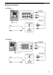
■Using one subwoofer Subwoofer To AC outlet Amplifier Subwoofer Amplifier To AC outlet CONNECTIONS Mono pin cable (not included) Audio pin cable (not included) Mono pin cable (not included) Audio pin cable (not included) 6
■Using one subwoofer Subwoofer To AC outlet Amplifier Subwoofer Amplifier To AC outlet CONNECTIONS Mono pin cable (not included) Audio pin cable (not included) Mono pin cable (not included) Audio pin cable (not included) 6
Owners Manual
Page 10
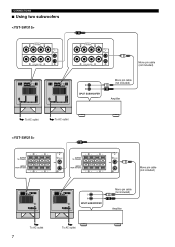
CONNECTIONS ■ Using two subwoofers To AC outlet To AC outlet To AC outlet 7 To AC outlet Mono pin cable (not included) Mono pin cable (not included) Amplifier Mono pin cable (not included) Mono pin cable (not included) Amplifier
CONNECTIONS ■ Using two subwoofers To AC outlet To AC outlet To AC outlet 7 To AC outlet Mono pin cable (not included) Mono pin cable (not included) Amplifier Mono pin cable (not included) Mono pin cable (not included) Amplifier
Owners Manual
Page 11
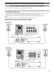
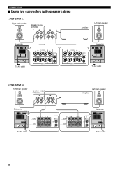
... so that both terminals can output sound signals simultaneously. • Connect one subwoofer (with speaker cables) Right main speaker Subwoofer Left main speaker To AC outlet Speaker output terminals Amplifier Right main speaker Subwoofer To AC outlet Speaker output terminals Left main speaker Amplifier 8 Note •... see page 10. ■ Using one set of main speaker output terminals of the amplifier to the INPUT1 terminals of the subwoofer, and connect the other set of main speaker output terminals of the amplifier to speaker output terminals of the amplifier Select this ...
... so that both terminals can output sound signals simultaneously. • Connect one subwoofer (with speaker cables) Right main speaker Subwoofer Left main speaker To AC outlet Speaker output terminals Amplifier Right main speaker Subwoofer To AC outlet Speaker output terminals Left main speaker Amplifier 8 Note •... see page 10. ■ Using one set of main speaker output terminals of the amplifier to the INPUT1 terminals of the subwoofer, and connect the other set of main speaker output terminals of the amplifier to speaker output terminals of the amplifier Select this ...
Owners Manual
Page 12
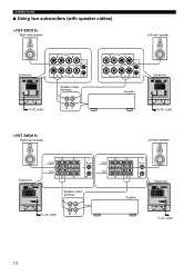
CONNECTIONS ■ Using two subwoofers (with speaker cables) Right main speaker Speaker output terminals Amplifier Left main speaker Subwoofer Subwoofer To AC outlet Right main speaker Speaker output terminals Subwoofer To AC outlet Amplifier Left main speaker Subwoofer To AC outlet To AC outlet 9
CONNECTIONS ■ Using two subwoofers (with speaker cables) Right main speaker Speaker output terminals Amplifier Left main speaker Subwoofer Subwoofer To AC outlet Right main speaker Speaker output terminals Subwoofer To AC outlet Amplifier Left main speaker Subwoofer To AC outlet To AC outlet 9

Owners Manual
Page 13
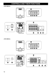
CONNECTIONS If your amplifier has only one subwoofer (with speaker cables) Right main speaker Left main speaker Subwoofer To AC outlet Right main speaker Speaker output terminals Amplifier Left main speaker Subwoofer To AC outlet Speaker output terminals Amplifier 10 Connect the speaker output terminals of the amplifier to the main speakers. ■ Using one set of the subwoofer to the INPUT1 terminals of the subwoofer, and connect the OUTPUT terminals of main speaker output terminals.
CONNECTIONS If your amplifier has only one subwoofer (with speaker cables) Right main speaker Left main speaker Subwoofer To AC outlet Right main speaker Speaker output terminals Amplifier Left main speaker Subwoofer To AC outlet Speaker output terminals Amplifier 10 Connect the speaker output terminals of the amplifier to the main speakers. ■ Using one set of the subwoofer to the INPUT1 terminals of the subwoofer, and connect the OUTPUT terminals of main speaker output terminals.
Owners Manual
Page 14
CONNECTIONS ■ Using two subwoofers (with speaker cables) Right main speaker Left main speaker Subwoofer Speaker output terminals To AC outlet Right main speaker Amplifier Subwoofer To AC outlet Left main speaker Subwoofer Speaker output terminals To AC outlet Amplifier Subwoofer To AC outlet 11
CONNECTIONS ■ Using two subwoofers (with speaker cables) Right main speaker Left main speaker Subwoofer Speaker output terminals To AC outlet Right main speaker Amplifier Subwoofer To AC outlet Left main speaker Subwoofer Speaker output terminals To AC outlet Amplifier Subwoofer To AC outlet 11

Owners Manual
Page 15
... wires touch each speaker cable by pulling lightly on the cable at the terminal. Red: positive (+) Black: negative (-) Plug in the subwoofer to the AC outlet After all connections are reversed, the sound will be unnatural and lack bass. To AC outlet To AC outlet 12 Good.... 4 Test the firmness of the connection by twisting the coating off. If these cables are completed, plug in the subwoofer and other , because this could damage the subwoofer or the amplifier, or both of them . ■Before connecting Remove the insulation coating at the extremity of each other...
... wires touch each speaker cable by pulling lightly on the cable at the terminal. Red: positive (+) Black: negative (-) Plug in the subwoofer to the AC outlet After all connections are reversed, the sound will be unnatural and lack bass. To AC outlet To AC outlet 12 Good.... 4 Test the firmness of the connection by twisting the coating off. If these cables are completed, plug in the subwoofer and other , because this could damage the subwoofer or the amplifier, or both of them . ■Before connecting Remove the insulation coating at the extremity of each other...
Owners Manual
Page 16
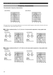
CONTROLS AND THEIR FUNCTIONS Front panel Rear panel (General model) Front panel Rear panel (General model) 13
CONTROLS AND THEIR FUNCTIONS Front panel Rear panel (General model) Front panel Rear panel (General model) 13

Owners Manual
Page 19
... adjustment again. • For adjusting the VOLUME control, the HIGH CUT control and the PHASE switch, refer to "Frequency characteristics" on the subwoofer. * The Power indicator lights up in green. 4 Play a source containing low-frequency components and adjust the amplifier's volume control to the ...frequency*. * The main speaker's rated minimum reproducible frequency can obtain a little more clearly.) • Once the volume balance between the subwoofer and the main speakers is not used. If the desired response cannot be obtained, set to the ON position, then press the STANDBY...
... adjustment again. • For adjusting the VOLUME control, the HIGH CUT control and the PHASE switch, refer to "Frequency characteristics" on the subwoofer. * The Power indicator lights up in green. 4 Play a source containing low-frequency components and adjust the amplifier's volume control to the ...frequency*. * The main speaker's rated minimum reproducible frequency can obtain a little more clearly.) • Once the volume balance between the subwoofer and the main speakers is not used. If the desired response cannot be obtained, set to the ON position, then press the STANDBY...
Owners Manual
Page 20
... 40 Hz 50 40 20 50 100 200 500Hz The figures below show the optimum adjustment of each control and the frequency characteristics when this subwoofer is combined with a typical main speaker system. ■ EX.1 When combined with a 4" or 5" (10 cm or 13 cm) acoustic suspension, 2 way system main speakers PHASE... : Set to the REV(reverse) position dB 90 80 YST-SW315 70 60 Main speaker 50 40 20 50 100 200 500Hz PHASE : Set to the REV(reverse) position dB 90 80...
... 40 Hz 50 40 20 50 100 200 500Hz The figures below show the optimum adjustment of each control and the frequency characteristics when this subwoofer is combined with a typical main speaker system. ■ EX.1 When combined with a 4" or 5" (10 cm or 13 cm) acoustic suspension, 2 way system main speakers PHASE... : Set to the REV(reverse) position dB 90 80 YST-SW315 70 60 Main speaker 50 40 20 50 100 200 500Hz PHASE : Set to the REV(reverse) position dB 90 80...

Owners Manual
Page 23
SPECIFICATIONS Type ........ Advanced Yamaha Active Servo Technology Driver .....25 cm (10") cone woofer (JA2564) Magnetic shielding type .......20 cm (8") cone woofer (JA2165) Magnetic shielding type Amplifier Output (100 Hz, 5 ohms, 10% THD)
SPECIFICATIONS Type ........ Advanced Yamaha Active Servo Technology Driver .....25 cm (10") cone woofer (JA2564) Magnetic shielding type .......20 cm (8") cone woofer (JA2165) Magnetic shielding type Amplifier Output (100 Hz, 5 ohms, 10% THD)

