Owner's Manual
Page 6
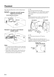
...8226; Keep enough ventilation space on the front, the rear, and the bottom side (that attached feet) of this unit in a pile. YST-FSW150 Foot YST-FSW050 Example 2: As a part of multi channel speaker system Upsidedown OK Upsidedown OK This unit Notes • Do not place this unit vertically....the feet. Note If vibrations of this unit may cause system failure, etc. Bottom view (example: YST-FSW150) Non-skid pads 2 En Example 1: Using this unit with Yamaha Digital Sound Projector Yamaha Digital Sound Projector This unit y Tip You can also place this unit toward a wall. Placement ...
...8226; Keep enough ventilation space on the front, the rear, and the bottom side (that attached feet) of this unit in a pile. YST-FSW150 Foot YST-FSW050 Example 2: As a part of multi channel speaker system Upsidedown OK Upsidedown OK This unit Notes • Do not place this unit vertically....the feet. Note If vibrations of this unit may cause system failure, etc. Bottom view (example: YST-FSW150) Non-skid pads 2 En Example 1: Using this unit with Yamaha Digital Sound Projector Yamaha Digital Sound Projector This unit y Tip You can also place this unit toward a wall. Placement ...
Owner's Manual
Page 7
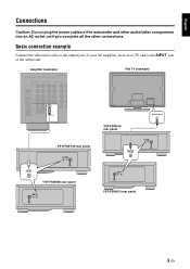
Amplifier (example) Flat TV (example) YST-FSW150 rear panel INPUT SYSTEM CONNECTOR INPUT YST-FSW050 rear panel SYSTEM INPUT CONNECTOR SUBWOOFER YST-FSW150 rear panel INPUT SUBWOOFER INPUT SYSTEM CONNECTOR SYSTEM INPUT CONNECTOR YST-FSW050 rear panel 3 En Basic connection example Connect the subwoofer cable to the output jack of your AV amplifier, receiver or TV and...
Amplifier (example) Flat TV (example) YST-FSW150 rear panel INPUT SYSTEM CONNECTOR INPUT YST-FSW050 rear panel SYSTEM INPUT CONNECTOR SUBWOOFER YST-FSW150 rear panel INPUT SUBWOOFER INPUT SYSTEM CONNECTOR SYSTEM INPUT CONNECTOR YST-FSW050 rear panel 3 En Basic connection example Connect the subwoofer cable to the output jack of your AV amplifier, receiver or TV and...
Owner's Manual
Page 8
... system control cable when connecting a Yamaha component equipped with the power button of this unit to OFF/ SYSTEM. VOLTAGE SELECTOR 220V-240V 110V-120V SYSTEM INPUT CONNECTOR YST-FSW050 rear panel 4 En YST-FSW150 rear panel INPUT SYSTEM CONNECTOR YST-FSW050 rear panel SYSTEM INPUT CONNECTOR To AC...50/60 Hz. The power mode of this unit must be set to the manual of the component. Yamaha Digital Sound Projector (example) SYSTEM CONNECTOR YST-FSW150 rear panel INPUT SYSTEM CONNECTOR SYSTEM CONNECTOR Connecting the components and the subwoofer to the AC power After ...
... system control cable when connecting a Yamaha component equipped with the power button of this unit to OFF/ SYSTEM. VOLTAGE SELECTOR 220V-240V 110V-120V SYSTEM INPUT CONNECTOR YST-FSW050 rear panel 4 En YST-FSW150 rear panel INPUT SYSTEM CONNECTOR YST-FSW050 rear panel SYSTEM INPUT CONNECTOR To AC...50/60 Hz. The power mode of this unit must be set to the manual of the component. Yamaha Digital Sound Projector (example) SYSTEM CONNECTOR YST-FSW150 rear panel INPUT SYSTEM CONNECTOR SYSTEM CONNECTOR Connecting the components and the subwoofer to the AC power After ...
Owner's Manual
Page 9
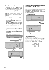
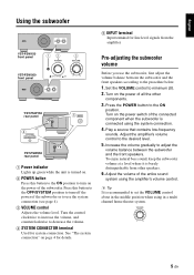
... front panel POWER VOLUME OFF/SYSTEM ON 0 10 12 POWER 3 VOLUME YST-FSW050 front panel OFF/SYSTEM ON 0 10 POWER VOLUME OFF/SYSTEM ON 0 10 YST-FSW150 rear panel INPUT SYSTEM CONNECTOR 5 INPUT 4 SYSTEM CONNECTOR YST-FSW050 rear panel SYSTEM INPUT CONNECTOR 1 Power indicator Lights up green while the unit is turned on. 2 POWER button...
... front panel POWER VOLUME OFF/SYSTEM ON 0 10 12 POWER 3 VOLUME YST-FSW050 front panel OFF/SYSTEM ON 0 10 POWER VOLUME OFF/SYSTEM ON 0 10 YST-FSW150 rear panel INPUT SYSTEM CONNECTOR 5 INPUT 4 SYSTEM CONNECTOR YST-FSW050 rear panel SYSTEM INPUT CONNECTOR 1 Power indicator Lights up green while the unit is turned on. 2 POWER button...
Owner's Manual
Page 12
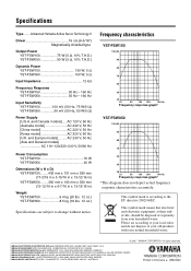
... Advanced Yamaha Active Servo Technology II Driver 16 cm (6-5/16") Magnetically shielded type Output Power YST-FSW150 75 W (5 Ω, 10% T.H.D.) YST-FSW050 50 W (5 Ω, 10% T.H.D.) Dynamic Power YST-FSW150 130 W, 5 Ω YST-FSW050 100 W, 5 Ω Input Impedance 12 kΩ Frequency Response YST-FSW150 30 Hz - 160 Hz YST-FSW050 35...-BEAUBOURG 77312 MARNE-LA-VALLEE CEDEX02, FRANCE YAMAHA ELECTRONICS (UK) LTD. Frequency characteristics YST-FSW150 100 dB 90 80 70 60 50 40 20 50 100 200 500 Hz Frequency response graph* YST-FSW050 100 dB 90 80 70 60 50 40...
... Advanced Yamaha Active Servo Technology II Driver 16 cm (6-5/16") Magnetically shielded type Output Power YST-FSW150 75 W (5 Ω, 10% T.H.D.) YST-FSW050 50 W (5 Ω, 10% T.H.D.) Dynamic Power YST-FSW150 130 W, 5 Ω YST-FSW050 100 W, 5 Ω Input Impedance 12 kΩ Frequency Response YST-FSW150 30 Hz - 160 Hz YST-FSW050 35...-BEAUBOURG 77312 MARNE-LA-VALLEE CEDEX02, FRANCE YAMAHA ELECTRONICS (UK) LTD. Frequency characteristics YST-FSW150 100 dB 90 80 70 60 50 40 20 50 100 200 500 Hz Frequency response graph* YST-FSW050 100 dB 90 80 70 60 50 40...

