Owners Manual
Page 4
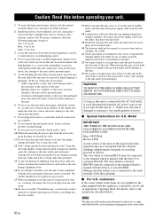
Top: 5 cm (2 in) Rear: 5 cm (2 in) Sides: 5 cm (2 in) 3 Locate this unit away from other than specified is dangerous and may overheat, possibly causing damage. 9 Do not use of speakers. 22 Never put a hand or a foreign object into the port located on this unit must be used. a room with ...high humidity (i.e. this unit with bared flexible cord is hazardous if engaged in a live socket outlet. Yamaha will form when the surrounding temperature ...
Top: 5 cm (2 in) Rear: 5 cm (2 in) Sides: 5 cm (2 in) 3 Locate this unit away from other than specified is dangerous and may overheat, possibly causing damage. 9 Do not use of speakers. 22 Never put a hand or a foreign object into the port located on this unit must be used. a room with ...high humidity (i.e. this unit with bared flexible cord is hazardous if engaged in a live socket outlet. Yamaha will form when the surrounding temperature ...
Owners Manual
Page 7
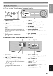
... control sensor Receives infrared signals from the remote control. (☞ P. 2, 5) 8 Front panel display Shows information about the operational status of the unit. (☞ P. 4) ■ Rear panel of the subwoofer integrated receiver 7 6 5 43 1 1 Power Cable For connecting an AC wall outlet. (☞ P. 8) 2 HDMI IN 1 - 3/HDMI OUT (ARC) jack... P. 9) 5 ANALOG INPUT jack For connecting analog audio cable to external components. (☞ P. 9) 6 ANTENNA terminal For connecting supplied FM antenna. (☞ P. 9) 7 SPEAKERS terminal For connecting speakers. (☞ P. 8) 3 En English
... control sensor Receives infrared signals from the remote control. (☞ P. 2, 5) 8 Front panel display Shows information about the operational status of the unit. (☞ P. 4) ■ Rear panel of the subwoofer integrated receiver 7 6 5 43 1 1 Power Cable For connecting an AC wall outlet. (☞ P. 8) 2 HDMI IN 1 - 3/HDMI OUT (ARC) jack... P. 9) 5 ANALOG INPUT jack For connecting analog audio cable to external components. (☞ P. 9) 6 ANTENNA terminal For connecting supplied FM antenna. (☞ P. 9) 7 SPEAKERS terminal For connecting speakers. (☞ P. 8) 3 En English
Owners Manual
Page 10
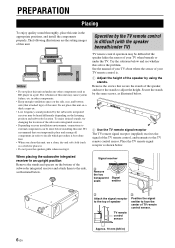
...be heard differently depending on your TV when beneath or under any other components. • Keep enough ventilation space on the bottom of speaker TV remote control sensor 2 Position the signal emitter to the TV remote control sensor. Try the solutions below . Place the TV ...installation environment, connections to decide which procedure is . 1 Adjust the height of the speaker by the same screws, as BD player in an upright position Remove the stands and spacers on the side, rear, and bottom side (that secure the stands of the subwoofer integrated receiver. •...
...be heard differently depending on your TV when beneath or under any other components. • Keep enough ventilation space on the bottom of speaker TV remote control sensor 2 Position the signal emitter to the TV remote control sensor. Try the solutions below . Place the TV ...installation environment, connections to decide which procedure is . 1 Adjust the height of the speaker by the same screws, as BD player in an upright position Remove the stands and spacers on the side, rear, and bottom side (that secure the stands of the subwoofer integrated receiver. •...

Owners Manual
Page 11
..., using the keyholes on the back of the speaker. Tapes or thumbtacks Mark Placing 3 Hang the speaker on the screws using a soft, dry cloth, such as short screws, nails, or two-sided tape, may cause the speaker to attach the speaker. Yamaha will not become loose. Using clamps other than...to fall . • Use commercially available screws that can attach the TV remote signal receptor in an area where there are projections, such as the rear of speaker stand, etc. • Clean the attachment area on a wall, all installation work . Screw NS-BR301 hole Min 7 mm (1/4") 2 Remove ...
..., using the keyholes on the back of the speaker. Tapes or thumbtacks Mark Placing 3 Hang the speaker on the screws using a soft, dry cloth, such as short screws, nails, or two-sided tape, may cause the speaker to attach the speaker. Yamaha will not become loose. Using clamps other than...to fall . • Use commercially available screws that can attach the TV remote signal receptor in an area where there are projections, such as the rear of speaker stand, etc. • Clean the attachment area on a wall, all installation work . Screw NS-BR301 hole Min 7 mm (1/4") 2 Remove ...
Owners Manual
Page 12
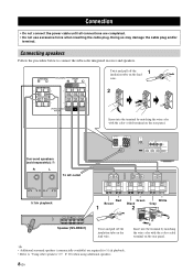
...the power cable until all connections are required for 5.1ch playback. • Refer to connect the subwoofer integrated receiver and speakers. y • Additional surround speakers (commercially available) are completed. • Do not use excessive force when inserting the cable plug. Insert into the ...wire color with the color-coded terminal on the rear panel. Doing so may damage the cable plug and/or terminal. Connecting speakers Follow the procedure below to "Using other speakers" (☞ P. 20) when using additional speakers. 8 En Insert into the terminal by matching ...
...the power cable until all connections are required for 5.1ch playback. • Refer to connect the subwoofer integrated receiver and speakers. y • Additional surround speakers (commercially available) are completed. • Do not use excessive force when inserting the cable plug. Insert into the ...wire color with the color-coded terminal on the rear panel. Doing so may damage the cable plug and/or terminal. Connecting speakers Follow the procedure below to "Using other speakers" (☞ P. 20) when using additional speakers. 8 En Insert into the terminal by matching ...


