
Owner's Manual
Page 2
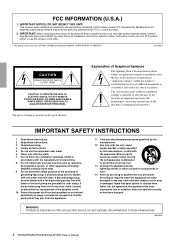
... Cable/s supplied with one wider than the other apparatus (including amplifiers) that may void your authority, granted by the ...ELECTRIC SHOCK, DO NOT EXPOSE THIS APPARATUS TO RAIN OR MOISTURE. (98-6500) 2 XP7000/XP5000/XP3500/XP2500/XP1000 Owner's Manual A polarized plug has two blades with this apparatus during lightning storms or when...into the apparatus, the apparatus has been exposed to persons. Modifications not expressly approved by YAMAHA CORPORATION OF AMERICA. (oscillator) CAUTION RISK OF ELECTRIC SHOCK DO NOT OPEN CAUTION: TO REDUCE THE...
... Cable/s supplied with one wider than the other apparatus (including amplifiers) that may void your authority, granted by the ...ELECTRIC SHOCK, DO NOT EXPOSE THIS APPARATUS TO RAIN OR MOISTURE. (98-6500) 2 XP7000/XP5000/XP3500/XP2500/XP1000 Owner's Manual A polarized plug has two blades with this apparatus during lightning storms or when...into the apparatus, the apparatus has been exposed to persons. Modifications not expressly approved by YAMAHA CORPORATION OF AMERICA. (oscillator) CAUTION RISK OF ELECTRIC SHOCK DO NOT OPEN CAUTION: TO REDUCE THE...
Owner's Manual
Page 5
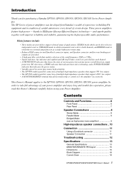
...in building PA equipment and its tradition of careful attention to the XP7000, XP5000, XP3500, XP2500, XP1000 power amplifier. The XP Series of power amplifiers was developed from Yamaha's wealth of experience in which the two internal amps function as high-power mono ...Manual 5 Main features include • Three modes are provided for purchasing a Yamaha XP7000, XP5000, XP3500, XP2500, XP1000 Series Power Amplifier. This Owner's Manual applies to every detail of your power amplifier and enjoy long and trouble-free operation, please read this Owner's ...
...in building PA equipment and its tradition of careful attention to the XP7000, XP5000, XP3500, XP2500, XP1000 power amplifier. The XP Series of power amplifiers was developed from Yamaha's wealth of experience in which the two internal amps function as high-power mono ...Manual 5 Main features include • Three modes are provided for purchasing a Yamaha XP7000, XP5000, XP3500, XP2500, XP1000 Series Power Amplifier. This Owner's Manual applies to every detail of your power amplifier and enjoy long and trouble-free operation, please read this Owner's ...
Owner's Manual
Page 6
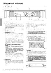
...equivalent to 1/2 W into an 8 Ω load, or 1 W into place using the same screws. 7 Air intakes The amplifier uses forced-air cooling. Front Rear 6 XP7000/XP5000/XP3500/XP2500/XP1000 Owner's Manual Air intake Air exhaust Controls and Functions ■ Front Panel 2 4 7 1 3 1 POWER switch ..., the protection system deactivates automatically and the amplifier is active. See the Precautions section of the heat sink rises above 1% - XP3500/2500/1000: The protection system is ready for approximately three seconds when the amplifier is ON. If a DC...
...equivalent to 1/2 W into an 8 Ω load, or 1 W into place using the same screws. 7 Air intakes The amplifier uses forced-air cooling. Front Rear 6 XP7000/XP5000/XP3500/XP2500/XP1000 Owner's Manual Air intake Air exhaust Controls and Functions ■ Front Panel 2 4 7 1 3 1 POWER switch ..., the protection system deactivates automatically and the amplifier is active. See the Precautions section of the heat sink rises above 1% - XP3500/2500/1000: The protection system is ready for approximately three seconds when the amplifier is ON. If a DC...
Owner's Manual
Page 7
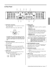
... monitoring or remote control. ■ Rear Panel 4 3 56 7 12 7 8 1 XLR inputs connectors These balanced XLR-3-31 type connectors are wired as a single mono amplifier. XP7000/XP5000/XP3500/XP2500/XP1000 Owner's Manual 7 The pins are used when changing the Gain of the A and B channels simultaneously. • +4dBu: The maximum output power...
... monitoring or remote control. ■ Rear Panel 4 3 56 7 12 7 8 1 XLR inputs connectors These balanced XLR-3-31 type connectors are wired as a single mono amplifier. XP7000/XP5000/XP3500/XP2500/XP1000 Owner's Manual 7 The pins are used when changing the Gain of the A and B channels simultaneously. • +4dBu: The maximum output power...
Owner's Manual
Page 8
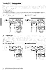
...the front panel (A and B) let you control the volume of each channel independently. Please be connected to the amplifier in the amplifier. Speaker Connections Speakers can be sure that speaker impedance will vary according to the B terminal. ●... 5-way binding post ● Speakon connector + - + - 4Ω* 4Ω* * Minimum speaker impedance 8 XP7000/XP5000/XP3500/XP2500/XP1000 Owner's Manual 4Ω* 4&#...
...the front panel (A and B) let you control the volume of each channel independently. Please be connected to the amplifier in the amplifier. Speaker Connections Speakers can be sure that speaker impedance will vary according to the B terminal. ●... 5-way binding post ● Speakon connector + - + - 4Ω* 4Ω* * Minimum speaker impedance 8 XP7000/XP5000/XP3500/XP2500/XP1000 Owner's Manual 4Ω* 4&#...
Owner's Manual
Page 9
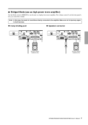
The volume control A on the front panel A lets you control the volume. Make sure not to input any signal to use as a high-power mono amplifier. Note: In this case, the loads for A and B are directly connected in the amplifier. ■ Bridged Mode (use the unit as high-power mono amplifier) Set the Mode switch to BRIDGE to the B terminal. ● 5-way binding post ● Speakon connector - + Minimum speaker impedance: 8Ω Minimum speaker impedance: 8Ω XP7000/XP5000/XP3500/XP2500/XP1000 Owner's Manual 9
The volume control A on the front panel A lets you control the volume. Make sure not to input any signal to use as a high-power mono amplifier. Note: In this case, the loads for A and B are directly connected in the amplifier. ■ Bridged Mode (use the unit as high-power mono amplifier) Set the Mode switch to BRIDGE to the B terminal. ● 5-way binding post ● Speakon connector - + Minimum speaker impedance: 8Ω Minimum speaker impedance: 8Ω XP7000/XP5000/XP3500/XP2500/XP1000 Owner's Manual 9
Owner's Manual
Page 11
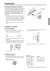
...top of the connector clockwise to fix the wires. 3 Attach the Euroblock connector to the input terminal on the rear of the amplifier, and turn the screws on top of a portable installation, we recommend that the bare wire ends do not jut out from... the terminals and touch the chassis. A- 1+ + 1- CHANNEL ı 1+ B+ 1- XP7000/XP5000/XP3500/XP2500/XP1000 Owner's Manual 11 CHANNEL Å STEREO or PARALLEL BRIDGE nector on the unit. Use a ferrule whose conductor portion has an external diameter of...
...top of the connector clockwise to fix the wires. 3 Attach the Euroblock connector to the input terminal on the rear of the amplifier, and turn the screws on top of a portable installation, we recommend that the bare wire ends do not jut out from... the terminals and touch the chassis. A- 1+ + 1- CHANNEL ı 1+ B+ 1- XP7000/XP5000/XP3500/XP2500/XP1000 Owner's Manual 11 CHANNEL Å STEREO or PARALLEL BRIDGE nector on the unit. Use a ferrule whose conductor portion has an external diameter of...
Owner's Manual
Page 12
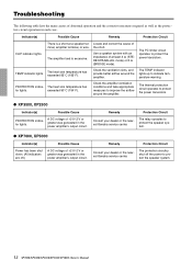
...The protection circuitry shut off .) A DC voltage of at a speaker terminal, amplifier terminal, or wire. The PC limiter circuit operates to protect the power transistors. ● XP3500, XP2500 Indicator(s) Possible Cause PROTECTION indicator lights. Locate and correct the cause of...) or 8 Ω (BRIDGE mode). The TEMP indicator lights up to protect the speaker system. 12 XP7000/XP5000/XP3500/XP2500/XP1000 Owner's Manual Remedy Protection Circuit Consult your dealer or the nearest Yamaha service center. Remedy Protection Circuit Consult your dealer or the nearest...
...The protection circuitry shut off .) A DC voltage of at a speaker terminal, amplifier terminal, or wire. The PC limiter circuit operates to protect the power transistors. ● XP3500, XP2500 Indicator(s) Possible Cause PROTECTION indicator lights. Locate and correct the cause of...) or 8 Ω (BRIDGE mode). The TEMP indicator lights up to protect the speaker system. 12 XP7000/XP5000/XP3500/XP2500/XP1000 Owner's Manual Remedy Protection Circuit Consult your dealer or the nearest Yamaha service center. Remedy Protection Circuit Consult your dealer or the nearest...
Owner's Manual
Page 14
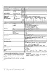
...Maximum Input Voltage Input Impedance Controls Front Panel Rear Panel Connectors Indicators Load Protection Input Output MONITOR/REMOTE POWER/STANDBY SIGNAL CLIP/LIMIT PROTECTION/TEMP Amplifier Protection Power Supply Protection Cooling Power Requirements Dimensions (W x H x D) Weight Included Accessories MIN MAX MAX MAX TYP MIN ...230 V/50 Hz A: 240 V/50 Hz 480 x 88 x 456 mm XP7000 14 kg XP5000 14 kg XP3500 15 kg XP2500 14 kg XP1000 12 kg Security cover (with your Yamaha dealer. operation not restored automatically. min, (DIN AUDIO) RL=8 Ω, 1 kHz Att. max, input...
...Maximum Input Voltage Input Impedance Controls Front Panel Rear Panel Connectors Indicators Load Protection Input Output MONITOR/REMOTE POWER/STANDBY SIGNAL CLIP/LIMIT PROTECTION/TEMP Amplifier Protection Power Supply Protection Cooling Power Requirements Dimensions (W x H x D) Weight Included Accessories MIN MAX MAX MAX TYP MIN ...230 V/50 Hz A: 240 V/50 Hz 480 x 88 x 456 mm XP7000 14 kg XP5000 14 kg XP3500 15 kg XP2500 14 kg XP1000 12 kg Security cover (with your Yamaha dealer. operation not restored automatically. min, (DIN AUDIO) RL=8 Ω, 1 kHz Att. max, input...
