
Owner's Manual
Page 2
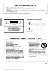
...does not operate normally, or has been dropped. Explanation of time. 14 Refer all servicing to persons. A polarized plug has two blades with arrowhead symbol within an equilateral triangle is used . When a cart is intended to alert the user to ... SAFETY INSTRUCTIONS 1 Read these instructions. 2 Keep these instructions. 3 Heed all warnings. 4 Follow all installation instructions. IMPORTANT: When connecting this apparatus near any way, such as power-supply cord or plug is intended to alert the user to products (XP7000, XP5000) distributed by Yamaha may be used , use the product...
...does not operate normally, or has been dropped. Explanation of time. 14 Refer all servicing to persons. A polarized plug has two blades with arrowhead symbol within an equilateral triangle is used . When a cart is intended to alert the user to ... SAFETY INSTRUCTIONS 1 Read these instructions. 2 Keep these instructions. 3 Heed all warnings. 4 Follow all installation instructions. IMPORTANT: When connecting this apparatus near any way, such as power-supply cord or plug is intended to alert the user to products (XP7000, XP5000) distributed by Yamaha may be used , use the product...
Owner's Manual
Page 3
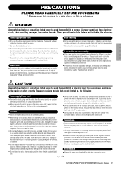
... , immediately turn off the power switch and disconnect the plug from becoming too high. In particular, do not excessively bend or otherwise damage the cord, place heavy objects on it, or place it in a position where anyone could walk on or off , electricity is turned off for all devices, set all volume levels to minimum. • Use only speaker cables for connecting speakers to...
... , immediately turn off the power switch and disconnect the plug from becoming too high. In particular, do not excessively bend or otherwise damage the cord, place heavy objects on it, or place it in a position where anyone could walk on or off , electricity is turned off for all devices, set all volume levels to minimum. • Use only speaker cables for connecting speakers to...
Owner's Manual
Page 4
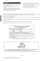
...; ed Yamaha service personnel about replacing defective components. Company names and product names used in the "STANDBY", electricity is still flowing to the device at a high or uncomfortable volume level, since this happens, turn on the device LAST, to avoid speaker damage. IMPORTANT NOTICE FOR THE UNITED KINGDOM Connecting the Plug and Cord WARNING: THIS APPARATUS MUST BE EARTHED IMPORTANT. The wire which...
...; ed Yamaha service personnel about replacing defective components. Company names and product names used in the "STANDBY", electricity is still flowing to the device at a high or uncomfortable volume level, since this happens, turn on the device LAST, to avoid speaker damage. IMPORTANT NOTICE FOR THE UNITED KINGDOM Connecting the Plug and Cord WARNING: THIS APPARATUS MUST BE EARTHED IMPORTANT. The wire which...
Owner's Manual
Page 5
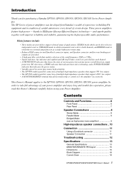
... Controls and Functions 6 Front Panel 6 Rear Panel 7 Speaker Connections 8 Stereo Mode 8 Parallel Mode 8 Bridged Mode (use as a single high-power mono amp. • Balanced XLR connector and Euroblock connector inputs, and Speakon connector and five-way binding post outputs are provided. • A high pass filter switch that enables selection of the cutoff frequency (20Hz or 55Hz). • Signal indicator, clip indicator and sophisticated dB step Volume control are provided for purchasing a Yamaha...
... Controls and Functions 6 Front Panel 6 Rear Panel 7 Speaker Connections 8 Stereo Mode 8 Parallel Mode 8 Bridged Mode (use as a single high-power mono amp. • Balanced XLR connector and Euroblock connector inputs, and Speakon connector and five-way binding post outputs are provided. • A high pass filter switch that enables selection of the cutoff frequency (20Hz or 55Hz). • Signal indicator, clip indicator and sophisticated dB step Volume control are provided for purchasing a Yamaha...
Owner's Manual
Page 6
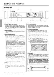
... high. 56 7 * The illustration shows model XP7000. 5 SIGNAL indicator Lights up in red and the speakers are automatically disconnected from the front and exhaust it through the rear. The fan speed will not be sure that the settings will then vary automatically as the temperature changes. Controls and Functions ■ Front Panel 2 4 7 1 3 1 POWER switch and indicator Press this Owner's Manual for ways to prevent the...
... high. 56 7 * The illustration shows model XP7000. 5 SIGNAL indicator Lights up in red and the speakers are automatically disconnected from the front and exhaust it through the rear. The fan speed will not be sure that the settings will then vary automatically as the temperature changes. Controls and Functions ■ Front Panel 2 4 7 1 3 1 POWER switch and indicator Press this Owner's Manual for ways to prevent the...
Owner's Manual
Page 7
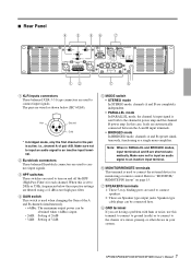
... turn on page 15. 7 SPEAKERS terminals 1: These 5-way binding posts are used to connect speakers. 2: These are used to the chassis of pair A/B. Refer to "MONITOR/ REMOTE PIN layout" on and off the HPF (High Pass Filter) for monitoring or remote control. XP7000/XP5000/XP3500/XP2500/XP1000 Owner's Manual 7 When this case, loads are completely independent. • PARALLEL mode In PARALLEL mode, the channel A input signal is set to the channel A power amp...
... turn on page 15. 7 SPEAKERS terminals 1: These 5-way binding posts are used to connect speakers. 2: These are used to the chassis of pair A/B. Refer to "MONITOR/ REMOTE PIN layout" on and off the HPF (High Pass Filter) for monitoring or remote control. XP7000/XP5000/XP3500/XP2500/XP1000 Owner's Manual 7 When this case, loads are completely independent. • PARALLEL mode In PARALLEL mode, the channel A input signal is set to the channel A power amp...
Owner's Manual
Page 8
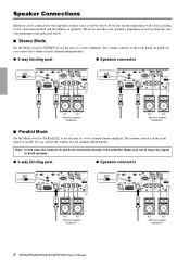
..., the loads for A and B are connected directly in three ways, as shown below . ■ Stereo Mode Set the Mode switch to STEREO to the B terminal. ● 5-way binding post ● Speakon connector + - + - 4Ω* 4Ω* * Minimum speaker impedance 8 XP7000/XP5000/XP3500/XP2500/XP1000 Owner's Manual 4Ω* 4Ω* * Minimum speaker impedance The volume controls on the front panel (A and B) let you control the volume of each channel independently. ● 5-way binding post ●...
..., the loads for A and B are connected directly in three ways, as shown below . ■ Stereo Mode Set the Mode switch to STEREO to the B terminal. ● 5-way binding post ● Speakon connector + - + - 4Ω* 4Ω* * Minimum speaker impedance 8 XP7000/XP5000/XP3500/XP2500/XP1000 Owner's Manual 4Ω* 4Ω* * Minimum speaker impedance The volume controls on the front panel (A and B) let you control the volume of each channel independently. ● 5-way binding post ●...
Owner's Manual
Page 9
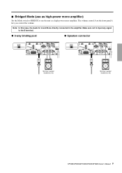
Make sure not to input any signal to use the unit as a high-power mono amplifier. The volume control A on the front panel A lets you control the volume. ■ Bridged Mode (use as high-power mono amplifier) Set the Mode switch to BRIDGE to the B terminal. ● 5-way binding post ● Speakon connector - + Minimum speaker impedance: 8Ω Minimum speaker impedance: 8Ω XP7000/XP5000/XP3500/XP2500/XP1000 Owner's Manual 9 Note: In this case, the loads for A and B are directly connected in the amplifier.
Make sure not to input any signal to use the unit as a high-power mono amplifier. The volume control A on the front panel A lets you control the volume. ■ Bridged Mode (use as high-power mono amplifier) Set the Mode switch to BRIDGE to the B terminal. ● 5-way binding post ● Speakon connector - + Minimum speaker impedance: 8Ω Minimum speaker impedance: 8Ω XP7000/XP5000/XP3500/XP2500/XP1000 Owner's Manual 9 Note: In this case, the loads for A and B are directly connected in the amplifier.
Owner's Manual
Page 10
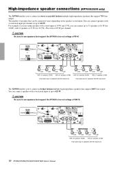
... x 31 speakers (310W) 15W x 21 speakers (315W) Total rated input of speakers: 625 W (maximum) 10 XP7000/XP5000/XP3500/XP2500/XP1000 Owner's Manual Be sure to use speakers that support the XP7000's line-out voltage of speakers that support 70V line output. You can connect speakers with a total rated input of up to 31 speakers at 10 W (for 310W), and 21 speakers at 15 W (for 315 W). High-impedance speaker connections (XP7000/3500...
... x 31 speakers (310W) 15W x 21 speakers (315W) Total rated input of speakers: 625 W (maximum) 10 XP7000/XP5000/XP3500/XP2500/XP1000 Owner's Manual Be sure to use speakers that support the XP7000's line-out voltage of speakers that support 70V line output. You can connect speakers with a total rated input of up to 31 speakers at 10 W (for 310W), and 21 speakers at 15 W (for 315 W). High-impedance speaker connections (XP7000/3500...
Owner's Manual
Page 11
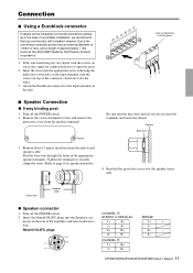
... protective cover over the speaker terminals. 15mm* * Actual size Speaker cable ● Speakon connector 1 Turn off the POWER switch. 2 Remove the cover attachment screws and remove the protective cover from the speaker terminals. XP7000/XP5000/XP3500/XP2500/XP1000 Owner's Manual 11 Connection ■ Using a Euroblock connector If cables will be frequently connected and disconnected, as the AI0,5-6WH made by the Phoenix Contact corporation). 1 If the wire...
... protective cover over the speaker terminals. 15mm* * Actual size Speaker cable ● Speakon connector 1 Turn off the POWER switch. 2 Remove the cover attachment screws and remove the protective cover from the speaker terminals. XP7000/XP5000/XP3500/XP2500/XP1000 Owner's Manual 11 Connection ■ Using a Euroblock connector If cables will be frequently connected and disconnected, as the AI0,5-6WH made by the Phoenix Contact corporation). 1 If the wire...
Owner's Manual
Page 12
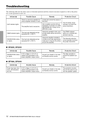
... indicators are off the power to protect the speaker system. 12 XP7000/XP5000/XP3500/XP2500/XP1000 Owner's Manual Locate and correct the cause of the short. The heat sink temperature has tor lights. Remedy Protection Circuit Consult your dealer or the nearest Yamaha service center. The PC limiter circuit operates to protect the power transistors. ● XP3500, XP2500 Indicator(s) Possible Cause PROTECTION indicator lights. PROTECTION indica- Check the...
... indicators are off the power to protect the speaker system. 12 XP7000/XP5000/XP3500/XP2500/XP1000 Owner's Manual Locate and correct the cause of the short. The heat sink temperature has tor lights. Remedy Protection Circuit Consult your dealer or the nearest Yamaha service center. The PC limiter circuit operates to protect the power transistors. ● XP3500, XP2500 Indicator(s) Possible Cause PROTECTION indicator lights. PROTECTION indica- Check the...
Owner's Manual
Page 14
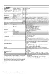
...;): Limit the output. operation not restored automatically. (XP7000, XP5000). Yamaha Corp. max, input 600 Ω shunt 20 Hz-20 kHz, Att. European models Purchaser/User Information specified in this owner's manual are for information purposes only. max, Rated Power 8 Ω Switch Position Maximum Input Voltage Input Impedance Controls Front Panel Rear Panel Connectors Indicators Load Protection Input Output MONITOR/REMOTE POWER/STANDBY SIGNAL CLIP/LIMIT PROTECTION/TEMP Amplifier Protection Power Supply Protection Cooling Power Requirements Dimensions...
...;): Limit the output. operation not restored automatically. (XP7000, XP5000). Yamaha Corp. max, input 600 Ω shunt 20 Hz-20 kHz, Att. European models Purchaser/User Information specified in this owner's manual are for information purposes only. max, Rated Power 8 Ω Switch Position Maximum Input Voltage Input Impedance Controls Front Panel Rear Panel Connectors Indicators Load Protection Input Output MONITOR/REMOTE POWER/STANDBY SIGNAL CLIP/LIMIT PROTECTION/TEMP Amplifier Protection Power Supply Protection Cooling Power Requirements Dimensions...
Owner's Manual
Page 15
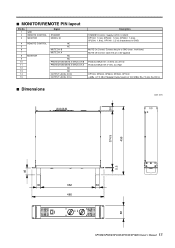
■ MONITOR/REMOTE PIN layout Pin No. 1 2 3 GND REMOTE CONTROL MONITOR Signal STANDBY MODEL ID 4 REMOTE CONTROL NC 5 NC 6 MUTE CH B 7 MUTE CH A 8 MONITOR NC 9 NC 10 PROTECTION/MUTE STATUS CH B 11 PROTECTION/MUTE STATUS CH A 12 NC 13 NC 14 OUTPUT LEVEL CH B 15 OUTPUT LEVEL CH A Description STANDBY Control: Supply 5 VDC, 5 mADC XP7000: 1.0 kΩ, XP5000: 1.2 kΩ, XP3500: 1.5 kΩ, XP2500: 1.8 kΩ, XP1000: 2.2 kΩ (Impedance to GND) MUTE On Control: Connect the pin to...
■ MONITOR/REMOTE PIN layout Pin No. 1 2 3 GND REMOTE CONTROL MONITOR Signal STANDBY MODEL ID 4 REMOTE CONTROL NC 5 NC 6 MUTE CH B 7 MUTE CH A 8 MONITOR NC 9 NC 10 PROTECTION/MUTE STATUS CH B 11 PROTECTION/MUTE STATUS CH A 12 NC 13 NC 14 OUTPUT LEVEL CH B 15 OUTPUT LEVEL CH A Description STANDBY Control: Supply 5 VDC, 5 mADC XP7000: 1.0 kΩ, XP5000: 1.2 kΩ, XP3500: 1.5 kΩ, XP2500: 1.8 kΩ, XP1000: 2.2 kΩ (Impedance to GND) MUTE On Control: Connect the pin to...
Owner's Manual
Page 16
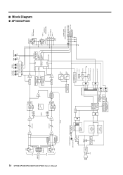
... B-1 - 5way DATA PORT (MONITOR/REMOTE) B OUTPUT LEVEL A OUTPUT LEVEL MUTE PROTECT STATUS STANDBY Model ID ■ Block Diagram ● XP7000/XP5000 16 XP7000/XP5000/XP3500/XP2500/XP1000 Owner's Manual CH A XLR 12 3 G INPUT [+22dBu MAX] - + G - + Euroblock CH B 12 3 XLR OFF HA BA HPF 20Hz 20Hz CH A ATT +4dBu +26dB +32dB HPF 55Hz 55Hz HPF 12dB/oct INV GAIN STEREO BRIDGE PARALLEL HA STEREO BRIDGE PARALLEL CH...
... B-1 - 5way DATA PORT (MONITOR/REMOTE) B OUTPUT LEVEL A OUTPUT LEVEL MUTE PROTECT STATUS STANDBY Model ID ■ Block Diagram ● XP7000/XP5000 16 XP7000/XP5000/XP3500/XP2500/XP1000 Owner's Manual CH A XLR 12 3 G INPUT [+22dBu MAX] - + G - + Euroblock CH B 12 3 XLR OFF HA BA HPF 20Hz 20Hz CH A ATT +4dBu +26dB +32dB HPF 55Hz 55Hz HPF 12dB/oct INV GAIN STEREO BRIDGE PARALLEL HA STEREO BRIDGE PARALLEL CH...
Owner's Manual
Page 17
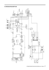
...OUTPUT (SPEAKERS) - CH A-1 + + CH B-1 - (A+B BRIDGE) 5way DATA PORT (MONITOR/REMOTE) B OUTPUT LEVEL A OUTPUT LEVEL MUTE PROTECT STATUS STANDBY Model ID ● XP3500/XP2500/XP1000 XP7000/XP5000/XP3500/XP2500/XP1000 Owner's Manual 17 CH A XLR 12 3 G INPUT - + [+22dBu MAX] G - + Euroblock CH B 12 3 XLR HA STEREO BRIDGE PARALLEL HA STEREO...SP RELAY MODE FAN CONTROL CIRCUIT POWER/STANDBY GR/OR (GR+RE) J destination only POWER SW Except J destination FG RELAY & LED DRIVE CIRCUIT PO SBY RELAY 1 RELAY 2 MAIN TRANS SUB TRANS 130˚C Thermal Thermal cutoff protector +24...
...OUTPUT (SPEAKERS) - CH A-1 + + CH B-1 - (A+B BRIDGE) 5way DATA PORT (MONITOR/REMOTE) B OUTPUT LEVEL A OUTPUT LEVEL MUTE PROTECT STATUS STANDBY Model ID ● XP3500/XP2500/XP1000 XP7000/XP5000/XP3500/XP2500/XP1000 Owner's Manual 17 CH A XLR 12 3 G INPUT - + [+22dBu MAX] G - + Euroblock CH B 12 3 XLR HA STEREO BRIDGE PARALLEL HA STEREO...SP RELAY MODE FAN CONTROL CIRCUIT POWER/STANDBY GR/OR (GR+RE) J destination only POWER SW Except J destination FG RELAY & LED DRIVE CIRCUIT PO SBY RELAY 1 RELAY 2 MAIN TRANS SUB TRANS 130˚C Thermal Thermal cutoff protector +24...
Owner's Manual
Page 18
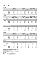
... 42 208 52 376 95 479 121 18 XP7000/XP5000/XP3500/XP2500/XP1000 Owner's Manual Test signal: Pink Noise, bandwidth limited from 22Hz to 22kHz 1W = 0.860kcal/h, 1BTU = 0.252kcal Note that Line Voltage [V] x Line Current [A] = [VA], not equals to these figures for most applications. 1/3 power represents program material with occasional clipping. Refer to [W]. ■ Current Draw XP7000...
... 42 208 52 376 95 479 121 18 XP7000/XP5000/XP3500/XP2500/XP1000 Owner's Manual Test signal: Pink Noise, bandwidth limited from 22Hz to 22kHz 1W = 0.860kcal/h, 1BTU = 0.252kcal Note that Line Voltage [V] x Line Current [A] = [VA], not equals to these figures for most applications. 1/3 power represents program material with occasional clipping. Refer to [W]. ■ Current Draw XP7000...
Owner's Manual
Page 19
..., Victoria 3006, Australia Tel: 3-9693-5111 COUNTRIES AND TRUST TERRITORIES IN PACIFIC OCEAN Yamaha Corporation, Asia-Pacific Music Marketing Group Nakazawa-cho 10-1, Naka-ku, Hamamatsu, Japan 430-8650 Tel: +81-53-460-2313 PA24 HEAD OFFICE Yamaha Corporation, Pro Audio & Digital Musical Instrument Division Nakazawa-cho 10-1, Naka-ku, Hamamatsu, Japan 430-8650 Tel: +81...
..., Victoria 3006, Australia Tel: 3-9693-5111 COUNTRIES AND TRUST TERRITORIES IN PACIFIC OCEAN Yamaha Corporation, Asia-Pacific Music Marketing Group Nakazawa-cho 10-1, Naka-ku, Hamamatsu, Japan 430-8650 Tel: +81-53-460-2313 PA24 HEAD OFFICE Yamaha Corporation, Pro Audio & Digital Musical Instrument Division Nakazawa-cho 10-1, Naka-ku, Hamamatsu, Japan 430-8650 Tel: +81...


