
Owner's Manual
Page 2
... input signal connected to channel A can be fed to take full advantage of your power amplifier and enjoy long and trouble-free operation, please read this apparatus may not correspond with superior reliability and stability, guaranteeing the highest possible audio performance. In order to the other channels using your plug, proceed as follows: The wire which is marked by the letter E or by YAMAHA KEMBLE MUSIC...
... input signal connected to channel A can be fed to take full advantage of your power amplifier and enjoy long and trouble-free operation, please read this apparatus may not correspond with superior reliability and stability, guaranteeing the highest possible audio performance. In order to the other channels using your plug, proceed as follows: The wire which is marked by the letter E or by YAMAHA KEMBLE MUSIC...
Owner's Manual
Page 3
...; Do not use this amplifier for normal ventilation. Contents Controls and Functions 4 Front Panel 4 Rear Panel 5 Connection 7 Using a Euroblock connector 7 Speaker Connection 7 Air Flow 8 Rack Mounting 8 Specifications 9 General Specifications 9 Block Diagram 10 Dimensions 11 Troubleshooting 12 3 Using the unit with wet hands. If the airflow is not adequate, the unit will heat up inside the unit, turn the power switch off immediately. Using other than driving loudspeakers. A damaged power cord is a potential...
...; Do not use this amplifier for normal ventilation. Contents Controls and Functions 4 Front Panel 4 Rear Panel 5 Connection 7 Using a Euroblock connector 7 Speaker Connection 7 Air Flow 8 Rack Mounting 8 Specifications 9 General Specifications 9 Block Diagram 10 Dimensions 11 Troubleshooting 12 3 Using the unit with wet hands. If the airflow is not adequate, the unit will heat up inside the unit, turn the power switch off immediately. Using other than driving loudspeakers. A damaged power cord is a potential...
Owner's Manual
Page 4
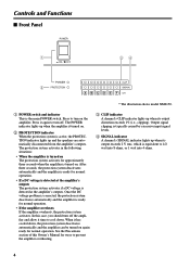
... caused by excessive input signal levels. 4 SIGNAL indicator A channel's SIGNAL indicator lights up and the speakers are automatically disconnected from the amplifier's outputs. See the Precautions section of this case, you should turn on . Controls and Functions s Front Panel 1 34 2 * The illustration shows model XM6150. 1 POWER switch and indicator This is detected at the amplifier's outputs. Press to 1/2 watt into 8 ohms, or 1 watt into 4 ohms. 4 Output signal clipping is equivalent to turn off . The protection system activates...
... caused by excessive input signal levels. 4 SIGNAL indicator A channel's SIGNAL indicator lights up and the speakers are automatically disconnected from the amplifier's outputs. See the Precautions section of this case, you should turn on . Controls and Functions s Front Panel 1 34 2 * The illustration shows model XM6150. 1 POWER switch and indicator This is detected at the amplifier's outputs. Press to 1/2 watt into 8 ohms, or 1 watt into 4 ohms. 4 Output signal clipping is equivalent to turn off . The protection system activates...
Owner's Manual
Page 5
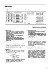
..., frequencies below 80 Hz are used . 5 When set to turn on and off the HPF (High Pass Filter) for each channel respectively. When set to BRIDGE, the signal connected to input channel A is amplified and output by the channel B outputs. For example, the signal connected to input channel A is active, i.e., channel A of the first channel in the pair is amplified and output by each channel. s Rear Panel 12 3 56 8 80 4 7 * The illustration shows model XM6150. 1 HPF switches...
..., frequencies below 80 Hz are used . 5 When set to turn on and off the HPF (High Pass Filter) for each channel respectively. When set to BRIDGE, the signal connected to input channel A is amplified and output by the channel B outputs. For example, the signal connected to input channel A is active, i.e., channel A of the first channel in the pair is amplified and output by each channel. s Rear Panel 12 3 56 8 80 4 7 * The illustration shows model XM6150. 1 HPF switches...
Owner's Manual
Page 6
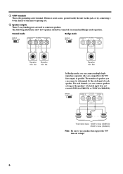
... 350W (for normal and Bridge mode operation. The following illustrations show how speakers should be connected for XM4220). -+ - + -+ Total rated input 150W or less (XM6150) 350W or less (XM4220) Note: Be sure to connector speakers. For each speaker. Speaker min. 4Ω Speaker min. 4Ω -+ Speaker min. 8Ω In Bridge mode, you can connect multiple highimpedance speakers (that are used to use speakers that support the 70V line-out voltage...
... 350W (for normal and Bridge mode operation. The following illustrations show how speakers should be connected for XM4220). -+ - + -+ Total rated input 150W or less (XM6150) 350W or less (XM4220) Note: Be sure to connector speakers. For each speaker. Speaker min. 4Ω Speaker min. 4Ω -+ Speaker min. 8Ω In Bridge mode, you can connect multiple highimpedance speakers (that are used to use speakers that support the 70V line-out voltage...
Owner's Manual
Page 7
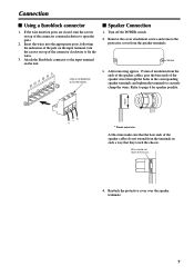
... clamp the wires. At this time make sure that they touch the chassis. Wire should not touch the chassis. 4. Turn off the POWER switch. 2. s Speaker Connection 1. Attach the Euroblock connector to open the ports. 2. Insert the wires into the appropriate ports, following the indication of the pole on the input terminal, turn the screws on the unit. Screw 3. Connection s Using a Euroblock connector 1. Use a screwdriver...
... clamp the wires. At this time make sure that they touch the chassis. Wire should not touch the chassis. 4. Turn off the POWER switch. 2. s Speaker Connection 1. Attach the Euroblock connector to open the ports. 2. Insert the wires into the appropriate ports, following the indication of the pole on the input terminal, turn the screws on the unit. Screw 3. Connection s Using a Euroblock connector 1. Use a screwdriver...
Owner's Manual
Page 8
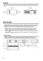
... top slot or the top panel of the rack and install a blanking panel between the rear panel of the rack and the rear panel of the amplifier. In particular, when mounting in a rack whose back can not be impaired. Air Flow This unit uses a forced cooling system in ...amps will cause the interior of the amp to become very hot, causing the performance of a panel on the left below is a dimensional diagram of the amps to the following instructions. Side View Front Rear View Air intake Air exhaust 80 Air exhaust Rack Mounting If multiple high-power amp units are installed. Fan: Use...
... top slot or the top panel of the rack and install a blanking panel between the rear panel of the rack and the rear panel of the amplifier. In particular, when mounting in a rack whose back can not be impaired. Air Flow This unit uses a forced cooling system in ...amps will cause the interior of the amp to become very hot, causing the performance of a panel on the left below is a dimensional diagram of the amps to the following instructions. Side View Front Rear View Air intake Air exhaust 80 Air exhaust Rack Mounting If multiple high-power amp units are installed. Fan: Use...
Owner's Manual
Page 9
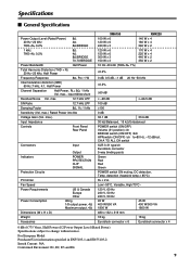
max.) Input Impedance Controls Front Panel Rear Panel Connectors Indicators Protection Circuits PC limiter Fan Speed Power Requirements Power Consumption Dimensions (W x H x D) Weight Accesaries Input Output POWER PROTECTION CLIP SIGNAL US & Canada Europe Other Idling 1/8 output power, 4Ω Maximum output, 4Ω XM6150 100 W x 6 120 W x 6 240 W x 3 120 W x 6 150 W x 6 300 W x 3 150 W x 3 10 Hz~40 kHz (THD+N= 1%) XM4220 140 W x 4 180 W x 4 360 W x 2 170 W x 4 220 W x 4 440 W x 2 350 W x 2 ≤0.2% 0 dB, 0.5 dB, -1 dB 20 Hz~50 kHz...
max.) Input Impedance Controls Front Panel Rear Panel Connectors Indicators Protection Circuits PC limiter Fan Speed Power Requirements Power Consumption Dimensions (W x H x D) Weight Accesaries Input Output POWER PROTECTION CLIP SIGNAL US & Canada Europe Other Idling 1/8 output power, 4Ω Maximum output, 4Ω XM6150 100 W x 6 120 W x 6 240 W x 3 120 W x 6 150 W x 6 300 W x 3 150 W x 3 10 Hz~40 kHz (THD+N= 1%) XM4220 140 W x 4 180 W x 4 360 W x 2 170 W x 4 220 W x 4 440 W x 2 350 W x 2 ≤0.2% 0 dB, 0.5 dB, -1 dB 20 Hz~50 kHz...

Owner's Manual
Page 10
s Block Diagram 10 Note: The block diagram indicated in the dotted frame ( ) applies only to model XM6150
s Block Diagram 10 Note: The block diagram indicated in the dotted frame ( ) applies only to model XM6150
Owner's Manual
Page 12
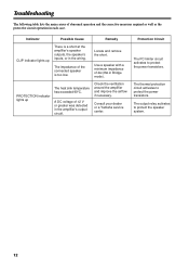
... voltage of ±2 V or greater was detected in each case. Use a speaker with a minimum impedance of the connected speaker is a short at the amplifier's speaker outputs, the speaker's inputs, or in Bridge mode). Protection Circuit The PC limiter circuit activates to protect the speaker system. 12 PROTECTION indicator lights up There is too low. The impedance of 4Ω (8Ω in the wiring. The thermal protection circuit activates to protect the power transistors.
... voltage of ±2 V or greater was detected in each case. Use a speaker with a minimum impedance of the connected speaker is a short at the amplifier's speaker outputs, the speaker's inputs, or in Bridge mode). Protection Circuit The PC limiter circuit activates to protect the speaker system. 12 PROTECTION indicator lights up There is too low. The impedance of 4Ω (8Ω in the wiring. The thermal protection circuit activates to protect the power transistors.


