
Quick Guide
Page 2
... Your Settings 9 4. Setup...21 7-1 Setting the internal clock 21 7-2 Initialization (factory reset 21 7-3 Attaching the optional Rack Mount Kit (RK5014) (TF1 only 21 8. Controls and functions 14 6-1 Channel Strip section 14 6-2 ST IN (Stereo Input) section 14 6-3 FX section 15 6-4 USER DEFINED... KEYS section 15 6-5 MUTE section 15 6-6 METER section 15 6-7 PHONES section 15 6-8 FADER BANK section 16 6-9 TAP section 16 6-10 SENDS ON FADER section 16 6-11 Display section 16 6-12 STEREO/MASTER section 20 6-13 iPad connector 20 6-14 USB connector 20 7. Contents 1.
... Your Settings 9 4. Setup...21 7-1 Setting the internal clock 21 7-2 Initialization (factory reset 21 7-3 Attaching the optional Rack Mount Kit (RK5014) (TF1 only 21 8. Controls and functions 14 6-1 Channel Strip section 14 6-2 ST IN (Stereo Input) section 14 6-3 FX section 15 6-4 USER DEFINED... KEYS section 15 6-5 MUTE section 15 6-6 METER section 15 6-7 PHONES section 15 6-8 FADER BANK section 16 6-9 TAP section 16 6-10 SENDS ON FADER section 16 6-11 Display section 16 6-12 STEREO/MASTER section 20 6-13 iPad connector 20 6-14 USB connector 20 7. Contents 1.

Quick Guide
Page 9
...'s monitor, and the amount of effects applied to each instrument. • Adjusting SENDS ON FADER for the level sent to AUX for each channel (page 16) • Muting all the settings for every channel in your mix. Adjust the Mix Adjust the overall balance of the mix After adjusting each channel...
...'s monitor, and the amount of effects applied to each instrument. • Adjusting SENDS ON FADER for the level sent to AUX for each channel (page 16) • Muting all the settings for every channel in your mix. Adjust the Mix Adjust the overall balance of the mix After adjusting each channel...

Quick Guide
Page 10
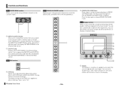
... (page 15) 4 USER DEFINED KEYS section (page 15) 5 MUTE section (page 15) ⑩ 6 METER section (page 15) 7 PHONES section (page 15) 8 FADER BANK section (page 16) 9 TAP key (page 16) 0 SENDS ON FADER section (page 16) ⑨ a Display section (page 16) b STEREO/MASTER section (page 20) c iPad connector (page 20) d USB connector (page 20)
... (page 15) 4 USER DEFINED KEYS section (page 15) 5 MUTE section (page 15) ⑩ 6 METER section (page 15) 7 PHONES section (page 15) 8 FADER BANK section (page 16) 9 TAP key (page 16) 0 SENDS ON FADER section (page 16) ⑨ a Display section (page 16) b STEREO/MASTER section (page 20) c iPad connector (page 20) d USB connector (page 20)

Quick Guide
Page 12
...if it is shown above. Default signal routing for each channel CHANNEL ANALOG INPUT TF5 TF3 CH 1 : CH 16 CH 17 : CH 24 CH 25 : CH 32 CH 33 : CH 40 ST IN 1L ST IN 1R...16 INPUT 17 : INPUT 24 INPUT 25 : INPUT 32 INPUT 1 : INPUT 8 ST IN 1L ST IN 1R ST IN 2L ST IN 2R INPUT 1 : INPUT 16 INPUT 17 : INPUT 24 INPUT 1 : INPUT 8 INPUT 9 : INPUT 16 ST IN 1L ST IN 1R ST IN 2L ST IN 2R TF1 INPUT 1 : INPUT 16... INPUT 1 : INPUT 8 INPUT 9 : INPUT 16 : ST IN 1L ST IN ...
...if it is shown above. Default signal routing for each channel CHANNEL ANALOG INPUT TF5 TF3 CH 1 : CH 16 CH 17 : CH 24 CH 25 : CH 32 CH 33 : CH 40 ST IN 1L ST IN 1R...16 INPUT 17 : INPUT 24 INPUT 25 : INPUT 32 INPUT 1 : INPUT 8 ST IN 1L ST IN 1R ST IN 2L ST IN 2R INPUT 1 : INPUT 16 INPUT 17 : INPUT 24 INPUT 1 : INPUT 8 INPUT 9 : INPUT 16 ST IN 1L ST IN 1R ST IN 2L ST IN 2R TF1 INPUT 1 : INPUT 16... INPUT 1 : INPUT 8 INPUT 9 : INPUT 16 : ST IN 1L ST IN ...

Quick Guide
Page 13
... Default signal routing for each output jack OMNI OUT 1 OMNI OUT 2 : OMNI OUT 12 OMNI OUT 13 OMNI OUT 14 OMNI OUT 15 (L) OMNI OUT 16 (R) AUX1 OUT AUX2 OUT : AUX12 OUT MONITOR L OUT MONITOR R OUT STEREO L OUT STEREO R OUT Each OMNI OUT jack is output on the SYSTEM OMNI OUT...
... Default signal routing for each output jack OMNI OUT 1 OMNI OUT 2 : OMNI OUT 12 OMNI OUT 13 OMNI OUT 14 OMNI OUT 15 (L) OMNI OUT 16 (R) AUX1 OUT AUX2 OUT : AUX12 OUT MONITOR L OUT MONITOR R OUT STEREO L OUT STEREO R OUT Each OMNI OUT jack is output on the SYSTEM OMNI OUT...
Quick Guide
Page 16
... key you tap on the display. The tempo you pressed lights to indicate SENDS ON FADER mode is currently selected. TF series Quick Guide ① - 16 - 1 [SENDS ON FADER] keys Press a key to set the corresponding bus to SENDS ON FADER mode. The keys light to indicate which fader bank is...
... key you tap on the display. The tempo you pressed lights to indicate SENDS ON FADER mode is currently selected. TF series Quick Guide ① - 16 - 1 [SENDS ON FADER] keys Press a key to set the corresponding bus to SENDS ON FADER mode. The keys light to indicate which fader bank is...

Quick Guide
Page 23
...bld. 7, Kievskaya street, Moscow, 121059, Russia Tel: 495 626 5005 OTHER EUROPEAN COUNTRIES Yamaha Music Europe GmbH Siemensstraße 22-34, 25462 Rellingen, Germany Tel: +49-4101-3030 AFRICA Yamaha Music Gulf FZE Office JAFZA 16-512, P.O.Box 17328, Jebel Ali - No:3, 34398 Şişli İstanbul... Europe GmbH Siemensstraße 22-34, 25462 Rellingen, Germany Tel: 04101-3030 OTHER COUNTRIES Yamaha Music Gulf FZE Office JAFZA 16-512, P.O.Box 17328, Jebel Ali - Tel: 02-2511-8688 THAILAND Siam Music Yamaha Co., Ltd. 3, 4, 15 and 16th floor, Siam Motors Building, 891/1 Rama 1 Road, ...
...bld. 7, Kievskaya street, Moscow, 121059, Russia Tel: 495 626 5005 OTHER EUROPEAN COUNTRIES Yamaha Music Europe GmbH Siemensstraße 22-34, 25462 Rellingen, Germany Tel: +49-4101-3030 AFRICA Yamaha Music Gulf FZE Office JAFZA 16-512, P.O.Box 17328, Jebel Ali - No:3, 34398 Şişli İstanbul... Europe GmbH Siemensstraße 22-34, 25462 Rellingen, Germany Tel: 04101-3030 OTHER COUNTRIES Yamaha Music Gulf FZE Office JAFZA 16-512, P.O.Box 17328, Jebel Ali - Tel: 02-2511-8688 THAILAND Siam Music Yamaha Co., Ltd. 3, 4, 15 and 16th floor, Siam Motors Building, 891/1 Rama 1 Road, ...

Reference Manual
Page 16
... back a WAV file, the file's sample rate and the current playback location are displayed here. B Record button Sets the console to edit the file's name. - 16 - Touch the music note icon to sort the items by that is currently playing is played and then playback stops. : SINGLE REPEAT;
... back a WAV file, the file's sample rate and the current playback location are displayed here. B Record button Sets the console to edit the file's name. - 16 - Touch the music note icon to sort the items by that is currently playing is played and then playback stops. : SINGLE REPEAT;

Reference Manual
Page 21
... off for AUX9/10-AUX19/20. 4 STEREO/SUB LINK (V1.1 and later) When turned on and off for 1. These buttons are linked. ձ 1 OMNI OUT1-16 buttons Allows you to the OMNI OUT jacks. ղ մ 1 AUX1/2-AUX7/8 signal type buttons Determines how each OMNI OUT jack is processed. OMNI OUT...
... off for AUX9/10-AUX19/20. 4 STEREO/SUB LINK (V1.1 and later) When turned on and off for 1. These buttons are linked. ձ 1 OMNI OUT1-16 buttons Allows you to the OMNI OUT jacks. ղ մ 1 AUX1/2-AUX7/8 signal type buttons Determines how each OMNI OUT jack is processed. OMNI OUT...

Reference Manual
Page 40
... be changed. ղ TF5: CH 1-32 TF3: CH 1-24 (when CH 1-24 are selected) CH 25-32 (when CH 25-32 are selected) TF1: CH 1-16 (when CH 1-16 are selected) CH 17-32 (when CH 17-32 are touching the button, gain for the left and right channels can be adjusted individually...
... be changed. ղ TF5: CH 1-32 TF3: CH 1-24 (when CH 1-24 are selected) CH 25-32 (when CH 25-32 are selected) TF1: CH 1-16 (when CH 1-16 are selected) CH 17-32 (when CH 17-32 are touching the button, gain for the left and right channels can be adjusted individually...

Reference Manual
Page 50
....0ms 1.0ms-1350.0ms 1.0ms-1350.0ms 1.0ms-1350.0ms -99 - +99 -99 - +99 -99 - +99 0.1-1.0 Thru, 21.2Hz-8.00kHz 50.0Hz-16.0kHz, Thru Off, On ----, - ----, - ----, - ----, - Right channel feedback gain. Parameter Reverb Time Initial Delay High Ratio Diffusion Density HPF LPF Range 0.3s-...20.0s 1.0ms-500.0ms 0.1-1.0 0-10 0% - 100% Thru, 21.2Hz-8.00kHz 50.0Hz-16.0kHz, Thru Description Determines the length of high-frequency feedback. High-pass filter cutoff frequency. Right channel delay time. Note C ----, - Center channel...
....0ms 1.0ms-1350.0ms 1.0ms-1350.0ms 1.0ms-1350.0ms -99 - +99 -99 - +99 -99 - +99 0.1-1.0 Thru, 21.2Hz-8.00kHz 50.0Hz-16.0kHz, Thru Off, On ----, - ----, - ----, - ----, - Right channel feedback gain. Parameter Reverb Time Initial Delay High Ratio Diffusion Density HPF LPF Range 0.3s-...20.0s 1.0ms-500.0ms 0.1-1.0 0-10 0% - 100% Thru, 21.2Hz-8.00kHz 50.0Hz-16.0kHz, Thru Description Determines the length of high-frequency feedback. High-pass filter cutoff frequency. Right channel delay time. Note C ----, - Center channel...

Reference Manual
Page 51
...Plate, Spring 0.1 - 20.0 0 - 10 1.0ms - 500.0ms 0 - 10 0% - 100% 1 - 19 -99% - 99% 0.1 - 1.0 Thru, 21.2Hz - 8.00kHz 50.0Hz - 16.0kHz, Thru Description Early reflection type. determines interval between early reflections. Width of the reflections in the stereo field. Amount of high frequency reverberations to... - 20.0 0 - 10 1.0ms - 500.0ms 0 - 10 0% - 100% 1 - 19 -99% - 99% 0.1 - 1.0 Thru, 21.2Hz - 8.00kHz 50.0Hz - 16.0kHz, Thru Description Early reflection type. Number of feedback. High-pass filter cutoff frequency. Amount of the reverberation. Left and right spread of feedback. Low...
...Plate, Spring 0.1 - 20.0 0 - 10 1.0ms - 500.0ms 0 - 10 0% - 100% 1 - 19 -99% - 99% 0.1 - 1.0 Thru, 21.2Hz - 8.00kHz 50.0Hz - 16.0kHz, Thru Description Early reflection type. determines interval between early reflections. Width of the reflections in the stereo field. Amount of high frequency reverberations to... - 20.0 0 - 10 1.0ms - 500.0ms 0 - 10 0% - 100% 1 - 19 -99% - 99% 0.1 - 1.0 Thru, 21.2Hz - 8.00kHz 50.0Hz - 16.0kHz, Thru Description Early reflection type. Number of feedback. High-pass filter cutoff frequency. Amount of the reverberation. Left and right spread of feedback. Low...

Reference Manual
Page 52
Delay time of phase shift stages. PHASER (V1.1 and later) Two-input, two-output 16-stage phase-shift effect. Number of modulation. Low-pass filter cutoff frequency. Low attack time. Configuration screens Description Mid threshold. High threshold. Delay Sync... Depth Feedback Gain Offset Phase Stage HPF LPF Sync Note Range 0.05Hz - 10.00Hz 0% - 100% -99% - 99% 0 - 100 0° - 355° 2 - 16 Thru, 21.2Hz - 8.00kHz 50.0Hz - 16.0kHz, Thru Off, On - Parameter tempo sync. Mid-band gain. High-band gain. Low threshold. Compression bypass feature for high. Mid ratio...
Delay time of phase shift stages. PHASER (V1.1 and later) Two-input, two-output 16-stage phase-shift effect. Number of modulation. Low-pass filter cutoff frequency. Low attack time. Configuration screens Description Mid threshold. High threshold. Delay Sync... Depth Feedback Gain Offset Phase Stage HPF LPF Sync Note Range 0.05Hz - 10.00Hz 0% - 100% -99% - 99% 0 - 100 0° - 355° 2 - 16 Thru, 21.2Hz - 8.00kHz 50.0Hz - 16.0kHz, Thru Off, On - Parameter tempo sync. Mid-band gain. High-band gain. Low threshold. Compression bypass feature for high. Mid ratio...

Reference Manual
Page 67
... strips depends on the left side of selected DCA group assigned to these channel strips DCA groups 1-8 assigned to manipulate the channels strips for the TF1. TF1: 1-8) The number of the console's top panel. (TF5: channel strips 25-32; This feature allows you to these channel strips - 67 -... Configuration screens TF Series Reference Manual TF1: 9-16) You can assign DCA groups 1-8 to the last 8 channel strips on the right side of channels in the group are assigned; TF3: 17-24;...
... strips depends on the left side of selected DCA group assigned to these channel strips DCA groups 1-8 assigned to manipulate the channels strips for the TF1. TF1: 1-8) The number of the console's top panel. (TF5: channel strips 25-32; This feature allows you to these channel strips - 67 -... Configuration screens TF Series Reference Manual TF1: 9-16) You can assign DCA groups 1-8 to the last 8 channel strips on the right side of channels in the group are assigned; TF3: 17-24;...
Reference Manual
Page 79
...Digital gain 39 Direct out 55 Displaying configuration screens..... 11 E EQ screen 41 EQ screen menu 44 F Fader Calibration screen 70 File information 16 Footswitch 27 FX screen (FX1/2, INS FX1-6) ....... 48 G GainFinder 39 GATE screen 44 Gateway 23 GEQ screen 62 Group channels 37 I...64 OVERVIEW screen 35 OVERVIEW screen operations ....... 37 P Peak Hold 13 Phantom power 20, 39 Phase 39 PHONES jack 18 Playback 14 Playback mode 16 Preset 8 R Recall on/off checkboxes 8 RECORDER screen (INPUT/ OUTPUT/TITLE LIST screen) ........ 14 RECORDER screen menu 17 Recording 14 RTA ...
...Digital gain 39 Direct out 55 Displaying configuration screens..... 11 E EQ screen 41 EQ screen menu 44 F Fader Calibration screen 70 File information 16 Footswitch 27 FX screen (FX1/2, INS FX1-6) ....... 48 G GainFinder 39 GATE screen 44 Gateway 23 GEQ screen 62 Group channels 37 I...64 OVERVIEW screen 35 OVERVIEW screen operations ....... 37 P Peak Hold 13 Phantom power 20, 39 Phase 39 PHONES jack 18 Playback 14 Playback mode 16 Preset 8 R Recall on/off checkboxes 8 RECORDER screen (INPUT/ OUTPUT/TITLE LIST screen) ........ 14 RECORDER screen menu 17 Recording 14 RTA ...

