
Quick Guide
Page 2
...21 7-1 Setting the internal clock 21 7-2 Initialization (factory reset 21 7-3 Attaching the optional Rack Mount Kit (RK5014) (TF1 only 21 8. Contents 1. Controls and functions 14 6-1 Channel Strip section 14 6-2 ST IN (Stereo Input) section 14 6-3 FX section 15 6-4 USER DEFINED KEYS section 15 6-5... MUTE section 15 6-6 METER section 15 6-7 PHONES section 15 6-8 FADER BANK section 16 6-9 TAP section 16 6-10 SENDS ON FADER section 16 6-11 Display section 16 ...
...21 7-1 Setting the internal clock 21 7-2 Initialization (factory reset 21 7-3 Attaching the optional Rack Mount Kit (RK5014) (TF1 only 21 8. Contents 1. Controls and functions 14 6-1 Channel Strip section 14 6-2 ST IN (Stereo Input) section 14 6-3 FX section 15 6-4 USER DEFINED KEYS section 15 6-5... MUTE section 15 6-6 METER section 15 6-7 PHONES section 15 6-8 FADER BANK section 16 6-9 TAP section 16 6-10 SENDS ON FADER section 16 6-11 Display section 16 ...

Quick Guide
Page 9
... of effects applied to each instrument. • Adjusting SENDS ON FADER for the level sent to AUX for each channel (page 16) • Muting all the settings for every channel in an instant and be ready for various types of instruments, so you can save a Scene by pressing and ... Presets and recreate that configuration anytime, easily. Saving a Scene Recalling a Scene When the console is a file stored in the Library ( ) that contains channel settings such as new Presets in the default state, USER DEFINED KEYS (page 15) are performing on / off , adjusting the overall level of effects (...
... of effects applied to each instrument. • Adjusting SENDS ON FADER for the level sent to AUX for each channel (page 16) • Muting all the settings for every channel in an instant and be ready for various types of instruments, so you can save a Scene by pressing and ... Presets and recreate that configuration anytime, easily. Saving a Scene Recalling a Scene When the console is a file stored in the Library ( ) that contains channel settings such as new Presets in the default state, USER DEFINED KEYS (page 15) are performing on / off , adjusting the overall level of effects (...

Quick Guide
Page 10
... sections. ① ⑬ ② ⑪ ③⑭ ④ ⑤ TF series Quick Guide ⑫ - 10 - ⑥ ⑦ ⑧ 1 Channel Strip section (page 14) 2 ST IN (stereo input) section (page 14) 3 FX (effects) section (page 15) 4 USER DEFINED KEYS section (page 15) 5 MUTE... section (page 15) ⑩ 6 METER section (page 15) 7 PHONES section (page 15) 8 FADER BANK section (page 16) 9 TAP key (page 16) 0 SENDS ON FADER section (page 16) ⑨ a Display section (page 16) b STEREO/MASTER section (page 20) c iPad connector (page 20) d USB connector (page 20) 4.
... sections. ① ⑬ ② ⑪ ③⑭ ④ ⑤ TF series Quick Guide ⑫ - 10 - ⑥ ⑦ ⑧ 1 Channel Strip section (page 14) 2 ST IN (stereo input) section (page 14) 3 FX (effects) section (page 15) 4 USER DEFINED KEYS section (page 15) 5 MUTE... section (page 15) ⑩ 6 METER section (page 15) 7 PHONES section (page 15) 8 FADER BANK section (page 16) 9 TAP key (page 16) 0 SENDS ON FADER section (page 16) ⑨ a Display section (page 16) b STEREO/MASTER section (page 20) c iPad connector (page 20) d USB connector (page 20) 4.

Quick Guide
Page 12
..., use the INPUT screen (page 18). Some direct boxes also need phantom power. When using condenser mics? Default signal routing for each channel CHANNEL ANALOG INPUT TF5 TF3 CH 1 : CH 16 CH 17 : CH 24 CH 25 : CH 32 CH 33 : CH 40 ST IN 1L ST IN 1R ST IN 2L ST... IN 1L ST IN 1R ST IN 2L ST IN 2R TF1 INPUT 1 : INPUT 16 INPUT 1 : INPUT 8 INPUT 9 : INPUT 16 : ST IN 1L ST IN 1R ST IN 2L ST IN 2R Default signal routing for each INPUT jack? • Is the channel's head amp gain set "+48V Master" on the SYSTEM SETUP screen...
..., use the INPUT screen (page 18). Some direct boxes also need phantom power. When using condenser mics? Default signal routing for each channel CHANNEL ANALOG INPUT TF5 TF3 CH 1 : CH 16 CH 17 : CH 24 CH 25 : CH 32 CH 33 : CH 40 ST IN 1L ST IN 1R ST IN 2L ST... IN 1L ST IN 1R ST IN 2L ST IN 2R TF1 INPUT 1 : INPUT 16 INPUT 1 : INPUT 8 INPUT 9 : INPUT 16 : ST IN 1L ST IN 1R ST IN 2L ST IN 2R Default signal routing for each INPUT jack? • Is the channel's head amp gain set "+48V Master" on the SYSTEM SETUP screen...
Quick Guide
Page 16
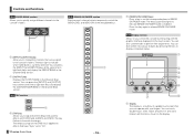
... displayed on the display. You can dive further into various features by interacting with the items shown on the touchscreen. TF series Quick Guide ① - 16 - 1 [SENDS ON FADER] keys Press a key to display contextual menus. ① ② ③ ④ ⑤ ⑦ ⑥ 1 Display The display ...indicate SENDS ON FADER mode is a multitouch capable touchscreen that are assigned to light both keys and display the CUSTOM FADER BANK in the Channel Strip section. You can press the [INPUT2] and [OUTPUT] keys at the same time to the console's faders. The key you to...
... displayed on the display. You can dive further into various features by interacting with the items shown on the touchscreen. TF series Quick Guide ① - 16 - 1 [SENDS ON FADER] keys Press a key to display contextual menus. ① ② ③ ④ ⑤ ⑦ ⑥ 1 Display The display ...indicate SENDS ON FADER mode is a multitouch capable touchscreen that are assigned to light both keys and display the CUSTOM FADER BANK in the Channel Strip section. You can press the [INPUT2] and [OUTPUT] keys at the same time to the console's faders. The key you to...

Reference Manual
Page 21
... are sent to the corresponding two buses will be assigned to the OMNI OUT jack you to configure the output channels that are only displayed if the Signal Type of the channel currently assigned to each OMNI OUT jack is processed. OMNI OUT screen menu Touch the Menu key ( ) from...OUT jacks. ղ մ 1 AUX1/2-AUX7/8 signal type buttons Determines how each pair of the STEREO channel and the SUB channel are linked. ձ 1 OMNI OUT1-16 buttons Allows you to select which output channel or monitor output will link with the Stereo bus pan setting. 3 AUX9/10-AUX19/20 Pan Link buttons...
... are sent to the corresponding two buses will be assigned to the OMNI OUT jack you to configure the output channels that are only displayed if the Signal Type of the channel currently assigned to each OMNI OUT jack is processed. OMNI OUT screen menu Touch the Menu key ( ) from...OUT jacks. ղ մ 1 AUX1/2-AUX7/8 signal type buttons Determines how each pair of the STEREO channel and the SUB channel are linked. ձ 1 OMNI OUT1-16 buttons Allows you to select which output channel or monitor output will link with the Stereo bus pan setting. 3 AUX9/10-AUX19/20 Pan Link buttons...

Reference Manual
Page 40
...when CH 1-24 are selected) CH 25-32 (when CH 25-32 are selected) TF1: CH 1-16 (when CH 1-16 are selected) CH 17-32 (when CH 17-32 are touching the button, gain for the left and right channels can be adjusted individually. Touch the input selection button that corresponds to assign the... INPUT jacks as the input source for all input channels. ձ 2 All USB icon ...
...when CH 1-24 are selected) CH 25-32 (when CH 25-32 are selected) TF1: CH 1-16 (when CH 1-16 are selected) CH 17-32 (when CH 17-32 are touching the button, gain for the left and right channels can be adjusted individually. Touch the input selection button that corresponds to assign the... INPUT jacks as the input source for all input channels. ձ 2 All USB icon ...

Reference Manual
Page 50
... LPF Sync Note Range 1.0ms-2700.0ms -99 - +99 0.1-1.0 Thru, 21.2Hz-8.00kHz 50.0Hz-16.0kHz, Thru Off, On ----, - Amount of the reverberation. Value used to calculate the left feedback gain. Right channel delay time. Right channel feedback gain. Value used to calculate the delay feedback time based on the tempo. Parameter...
... LPF Sync Note Range 1.0ms-2700.0ms -99 - +99 0.1-1.0 Thru, 21.2Hz-8.00kHz 50.0Hz-16.0kHz, Thru Off, On ----, - Amount of the reverberation. Value used to calculate the left feedback gain. Right channel delay time. Right channel feedback gain. Value used to calculate the delay feedback time based on the tempo. Parameter...

Reference Manual
Page 67
TF3: 17-24; Member channels of selected DCA group assigned to these channel strips DCA groups 1-8 assigned to manipulate the channels strips for the TF1. TF1: 9-16) You can assign DCA groups 1-8 to the last 8 channel strips on the right side of the console's top panel. (TF5: channel strips 25-32; TF3: 1-16; the lowest 16 for the TF 3, and the...
TF3: 17-24; Member channels of selected DCA group assigned to these channel strips DCA groups 1-8 assigned to manipulate the channels strips for the TF1. TF1: 9-16) You can assign DCA groups 1-8 to the last 8 channel strips on the right side of the console's top panel. (TF5: channel strips 25-32; TF3: 1-16; the lowest 16 for the TF 3, and the...
Reference Manual
Page 79
... 11 E EQ screen 41 EQ screen menu 44 F Fader Calibration screen 70 File information 16 Footswitch 27 FX screen (FX1/2, INS FX1-6) ....... 48 G GainFinder 39 GATE screen 44 Gateway 23 GEQ screen 62 Group channels 37 I Initialize (internal memory 68 Initialize All Memory screen 68 Initialize Current Memory screen .......Scene 11 SCENE screen 11 SCENE screen menu 12 SEND FROM screen 65 Send pan 65 SEND TO AUX screen 53 Stereo channels 35 Stereo link 39 SUB channels 36 Subnet mask 23 SYSTEM SETUP screen 20 T Time stamp 24 Toolbar 11 U USER DEFINED KEYS 26 USER DEFINED KNOBS...
... 11 E EQ screen 41 EQ screen menu 44 F Fader Calibration screen 70 File information 16 Footswitch 27 FX screen (FX1/2, INS FX1-6) ....... 48 G GainFinder 39 GATE screen 44 Gateway 23 GEQ screen 62 Group channels 37 I Initialize (internal memory 68 Initialize All Memory screen 68 Initialize Current Memory screen .......Scene 11 SCENE screen 11 SCENE screen menu 12 SEND FROM screen 65 Send pan 65 SEND TO AUX screen 53 Stereo channels 35 Stereo link 39 SUB channels 36 Subnet mask 23 SYSTEM SETUP screen 20 T Time stamp 24 Toolbar 11 U USER DEFINED KEYS 26 USER DEFINED KNOBS...


