
Owner's Manual
Page 2
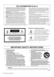
...! This equipment generates/uses radio frequencies and, if not installed and used according to the instructions found to constitute a risk of time. 14 Refer all installation instructions. Compliance with this product MUST be determined by turning the unit "OFF" and "ON", please try to eliminate the problem by Yamaha may be of sufficient magnitude to be the source of the following...
...! This equipment generates/uses radio frequencies and, if not installed and used according to the instructions found to constitute a risk of time. 14 Refer all installation instructions. Compliance with this product MUST be determined by turning the unit "OFF" and "ON", please try to eliminate the problem by Yamaha may be of sufficient magnitude to be the source of the following...
Owner's Manual
Page 3
The device contains no user-serviceable parts. Even when the power switch is easily accessible. When you are not using is turned off the power switch and disconnect the plug from the device or an outlet, always hold the plug itself and in the TV or radio next to it. • Do not place the device in...device has ventilation holes at the front/rear to prevent the internal temperature from the outlet when the device is a sudden loss of sound during the day) to prevent the possibility of panel disfiguration or damage to the internal components. • Do not place the device...
The device contains no user-serviceable parts. Even when the power switch is easily accessible. When you are not using is turned off the power switch and disconnect the plug from the device or an outlet, always hold the plug itself and in the TV or radio next to it. • Do not place the device in...device has ventilation holes at the front/rear to prevent the internal temperature from the outlet when the device is a sudden loss of sound during the day) to prevent the possibility of panel disfiguration or damage to the internal components. • Do not place the device...
Owner's Manual
Page 4
... in this happens, turn the power off FIRST for a long period of components with the coloured markings identifying the terminals in your audio system, always turn off for all devices, set all volume levels to minimum. • Use only speaker cables for all devices. Yamaha cannot be turned off when the device is not in your plug proceed as follows: The wire which is marked...
... in this happens, turn the power off FIRST for a long period of components with the coloured markings identifying the terminals in your audio system, always turn off for all devices, set all volume levels to minimum. • Use only speaker cables for all devices. Yamaha cannot be turned off when the device is not in your plug proceed as follows: The wire which is marked...
Owner's Manual
Page 5
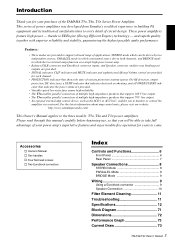
... Two Euroblock connectors Index Controls and Functions 6 Front Panel 6 Rear Panel 7 Speaker Connections 8 STEREO Mode 8 PARALLEL Mode 8 BRIDGE Mode 9 Wiring 9 Using a Euroblock connector 9 Speaker Connection 10 Filter Element Cleaning 11 Troubleshooting 11 Specifications 12 Block Diagram 71 Dimensions 72 Performance Graph 73 Current Draw 73 T5n/T4n/T3n Owner's Manual 5 Features: • Three modes are provided to support a broad range of applications: STEREO mode which the two internal amps function as a single high-power mono amp. • Balanced XLR connector and...
... Two Euroblock connectors Index Controls and Functions 6 Front Panel 6 Rear Panel 7 Speaker Connections 8 STEREO Mode 8 PARALLEL Mode 8 BRIDGE Mode 9 Wiring 9 Using a Euroblock connector 9 Speaker Connection 10 Filter Element Cleaning 11 Troubleshooting 11 Specifications 12 Block Diagram 71 Dimensions 72 Performance Graph 73 Current Draw 73 T5n/T4n/T3n Owner's Manual 5 Features: • Three modes are provided to support a broad range of applications: STEREO mode which the two internal amps function as a single high-power mono amp. • Balanced XLR connector and...
Owner's Manual
Page 6
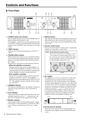
... the heat sink temperature: It operates at low speed when it through the rear. Controls and Functions ■ Front Panel 2 656 T5n 0 9 1 43 78 9 0 1 POWER switch and indicator Press to enter STANDBY mode, this indicator will be sure that "clipping" has occurred because the signal level is too high. 6 SIGNAL indicator Lights up red when the output signal distortion on the corresponding channel rises above 1% - Also, clean the...
... the heat sink temperature: It operates at low speed when it through the rear. Controls and Functions ■ Front Panel 2 656 T5n 0 9 1 43 78 9 0 1 POWER switch and indicator Press to enter STANDBY mode, this indicator will be sure that "clipping" has occurred because the signal level is too high. 6 SIGNAL indicator Lights up red when the output signal distortion on the corresponding channel rises above 1% - Also, clean the...
Owner's Manual
Page 7
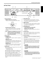
... audio signal to an inactive input terminal (channel B). 2 Mode switch • STEREO mode In STEREO mode, channels A and B are having a problem with mounting hardware that it can be used to set the amplifier's ID. 6 SPEAKERS jacks • 5-way binding post output jacks • Speakon type output jacks Speakon type cable plugs (Neutrik NL4) can demand high current from the AC service. The Channel B input connector does not function. • BRIDGE mode In BRIDGE mode, channels A and B operates simultaneously, functioning...
... audio signal to an inactive input terminal (channel B). 2 Mode switch • STEREO mode In STEREO mode, channels A and B are having a problem with mounting hardware that it can be used to set the amplifier's ID. 6 SPEAKERS jacks • 5-way binding post output jacks • Speakon type output jacks Speakon type cable plugs (Neutrik NL4) can demand high current from the AC service. The Channel B input connector does not function. • BRIDGE mode In BRIDGE mode, channels A and B operates simultaneously, functioning...
Owner's Manual
Page 8
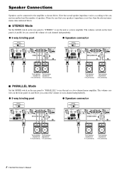
.../T4n/T3n Owner's Manual The volume controls on the front panel (A and B) let you control the volume of speakers. Speaker Connections Speakers can be sure that actual speaker impedance varies according to the connection method and the number of each channel independently. ● 5-way binding post ● Speakon connector + - + - Total speaker Total speaker impedance: impedance: 2 Ω (minimum) 2 Ω (minimum) Total speaker impedance: 2 Ω (minimum) Total speaker impedance: 2 Ω (minimum) ■ PARALLEL Mode Set the MODE switch on the rear panel to...
.../T4n/T3n Owner's Manual The volume controls on the front panel (A and B) let you control the volume of speakers. Speaker Connections Speakers can be sure that actual speaker impedance varies according to the connection method and the number of each channel independently. ● 5-way binding post ● Speakon connector + - + - Total speaker Total speaker impedance: impedance: 2 Ω (minimum) 2 Ω (minimum) Total speaker impedance: 2 Ω (minimum) Total speaker impedance: 2 Ω (minimum) ■ PARALLEL Mode Set the MODE switch on the rear panel to...
Owner's Manual
Page 9
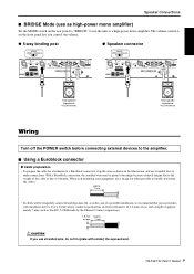
... with insulation sleeves. With a Euroblock connection, the stranded wire may be frequently connected and disconnected, as in the illustration, and use stranded wire to vibration. The volume control A on the rear panel to "BRIDGE" to bundle and fasten the cables. Speaker Connections Speaker Connections ■ BRIDGE Mode (use as high-power mono amplifier) Set the MODE switch on the front panel lets you control the volume. ● 5-way binding post ●...
... with insulation sleeves. With a Euroblock connection, the stranded wire may be frequently connected and disconnected, as in the illustration, and use stranded wire to vibration. The volume control A on the rear panel to "BRIDGE" to bundle and fasten the cables. Speaker Connections Speaker Connections ■ BRIDGE Mode (use as high-power mono amplifier) Set the MODE switch on the front panel lets you control the volume. ● 5-way binding post ●...
Owner's Manual
Page 10
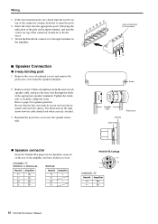
... page 8 for speaker polarities. Reattach the protective cover over the speaker terminals. 15mm* Use a screwdriver to fix the wires. -G + Screw Speaker cable * Actual size Chassis Bare wire ● Speakon connector Insert the Neutrik NL4 plugs into the appropriate ports, following the indication of the pole on the input terminal, and turn the screws on the amplifier. ■ Speaker Connection ● 5-way...
... page 8 for speaker polarities. Reattach the protective cover over the speaker terminals. 15mm* Use a screwdriver to fix the wires. -G + Screw Speaker cable * Actual size Chassis Bare wire ● Speakon connector Insert the Neutrik NL4 plugs into the appropriate ports, following the indication of the pole on the input terminal, and turn the screws on the amplifier. ■ Speaker Connection ● 5-way...
Owner's Manual
Page 11
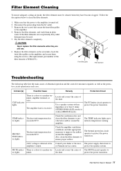
.... protect the power transistors. Follow the description below to amplifier's output. Locate and correct the cause of at a speaker ter- the short. TEMP indica- Indicator(s) Possible Cause Remedy Protection Circuit CLIP indicator lights. Remove the filter elements, and wash them using the screws. (The replacement part number of the filter element is a short at least 2 ohms (STEREO/PARALLEL mode...
.... protect the power transistors. Follow the description below to amplifier's output. Locate and correct the cause of at a speaker ter- the short. TEMP indica- Indicator(s) Possible Cause Remedy Protection Circuit CLIP indicator lights. Remove the filter elements, and wash them using the screws. (The replacement part number of the filter element is a short at least 2 ohms (STEREO/PARALLEL mode...
Owner's Manual
Page 13
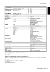
....) VI limiter (RL ≤ 1 Ω): Limit the output. European models Purchaser/User Information specified in this owner's manual are for information purposes only. Max, input 600 Ω shunt RL = 8 Ω, 1 kHz Att. Max Front Panel Rear Panel Connectors Indicators Load Protection Input Output DATA PORT POWER/STANDBY REMOTE PROTECTION TEMP SIGNAL MUTE CLIP Amplifier Protection Power Supply Protection Cooling Power Requirements Power Cord Length Dimensions (W x H x D) Weight Included Accessories These...
....) VI limiter (RL ≤ 1 Ω): Limit the output. European models Purchaser/User Information specified in this owner's manual are for information purposes only. Max, input 600 Ω shunt RL = 8 Ω, 1 kHz Att. Max Front Panel Rear Panel Connectors Indicators Load Protection Input Output DATA PORT POWER/STANDBY REMOTE PROTECTION TEMP SIGNAL MUTE CLIP Amplifier Protection Power Supply Protection Cooling Power Requirements Power Cord Length Dimensions (W x H x D) Weight Included Accessories These...
Owner's Manual
Page 14
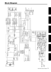
... (POWER ON) STANDBY (REMOTE) DRIVER REMOTE TEMP PROTECTION DRIVER +5V CH A CH B DRIVER CH A CH B +5V CH A CH B POWER/STANDBY GR/OR (GR+RE) REMOTE GR TEMP RE PROTECTION RE CLIP/LIMIT RE OUTPUT SIGNAL GR MUTE RE MODEL ID INPUT V MONITOR MODE PHASE CONTROL LEVEL CONTROL REMOTE ELECTRIC VARIABLE RESISTANCE Block Diagram T5n/T4n/T3n Owner's Manual 71 INPUT [+24dBu] MAX CH A 3 12 GAIN -3.4dB BA G - + G - + CH B 3 12 FG GAIN -3.4dB BA STEREO BRIDGE PARALLEL STEREO BRIDGE PARALLEL MODE...
... (POWER ON) STANDBY (REMOTE) DRIVER REMOTE TEMP PROTECTION DRIVER +5V CH A CH B DRIVER CH A CH B +5V CH A CH B POWER/STANDBY GR/OR (GR+RE) REMOTE GR TEMP RE PROTECTION RE CLIP/LIMIT RE OUTPUT SIGNAL GR MUTE RE MODEL ID INPUT V MONITOR MODE PHASE CONTROL LEVEL CONTROL REMOTE ELECTRIC VARIABLE RESISTANCE Block Diagram T5n/T4n/T3n Owner's Manual 71 INPUT [+24dBu] MAX CH A 3 12 GAIN -3.4dB BA G - + G - + CH B 3 12 FG GAIN -3.4dB BA STEREO BRIDGE PARALLEL STEREO BRIDGE PARALLEL MODE...
Owner's Manual
Page 16
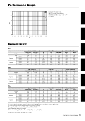
... (120V), 14A (240V) T5n/T4n/T3n Owner's Manual 73 Test signal: Pink Noise, bandwidth limited from 22Hz to 22kHz 1W = 0.860kcal/h, 1BTU = 0.252kcal Note that Line Voltage [V] x Line Current [A] = [VA], not equals to these figures for most applications. 1/3 power represents program material with occasional clipping. Performance Graph dBr +2 FREQUENCY RESPONSE INPUT: Ch A/B (XLR 150 ohm) OUTPUT: Ch A/B (8 ohm) 0 dBr = 1 W +0 ATT: MAX -2 -4 -6 -8 10...
... (120V), 14A (240V) T5n/T4n/T3n Owner's Manual 73 Test signal: Pink Noise, bandwidth limited from 22Hz to 22kHz 1W = 0.860kcal/h, 1BTU = 0.252kcal Note that Line Voltage [V] x Line Current [A] = [VA], not equals to these figures for most applications. 1/3 power represents program material with occasional clipping. Performance Graph dBr +2 FREQUENCY RESPONSE INPUT: Ch A/B (XLR 150 ohm) OUTPUT: Ch A/B (8 ohm) 0 dBr = 1 W +0 ATT: MAX -2 -4 -6 -8 10...

Owner's Manual
Page 17
... Group Nakazawa-cho 10-1, Naka-ku, Hamamatsu, Japan 430-8650 Tel: +81-53-460-2313 PA24 HEAD OFFICE Yamaha Corporation, Pro Audio & Digital Musical Instrument Division Nakazawa-cho 10-1, Naka-ku, Hamamatsu, Japan 430-8650 Tel: +81-53-460-2441 Rua Joaquim Floriano, 913 - 4' andar, Itaim Bibi, CEP 04534-...
... Group Nakazawa-cho 10-1, Naka-ku, Hamamatsu, Japan 430-8650 Tel: +81-53-460-2313 PA24 HEAD OFFICE Yamaha Corporation, Pro Audio & Digital Musical Instrument Division Nakazawa-cho 10-1, Naka-ku, Hamamatsu, Japan 430-8650 Tel: +81-53-460-2441 Rua Joaquim Floriano, 913 - 4' andar, Itaim Bibi, CEP 04534-...


