Owner's Manual
Page 4
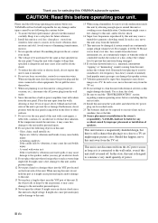
...electric shock since this manual carefully. away from the turntable. 17 This unit may be liable for any damage and/or injury caused by this YAMAHA subwoofer system. When moving this unit, do not hold the port as that specified on the rear panel. A burning candle etc. If the ...shock. 16 Super-bass frequencies reproduced by not following the cautions below. 1 To assure the finest performance, please read this unit uses a high voltage. YAMAHA will radiate from the wall outlet. 8 Since this unit itself is turned off. Using this unit away from windows, heat sources, sources of a ...
...electric shock since this manual carefully. away from the turntable. 17 This unit may be liable for any damage and/or injury caused by this YAMAHA subwoofer system. When moving this unit, do not hold the port as that specified on the rear panel. A burning candle etc. If the ...shock. 16 Super-bass frequencies reproduced by not following the cautions below. 1 To assure the finest performance, please read this unit uses a high voltage. YAMAHA will radiate from the wall outlet. 8 Since this unit itself is turned off. Using this unit away from windows, heat sources, sources of a ...
Owner's Manual
Page 5
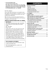
...the instructions described below. The wire which is hazardous if engaged in your amplifier 15 Frequency response 16 Advanced Yamaha Active Servo Technology II 17 TROUBLESHOOTING 18 SPECIFICATIONS 19 FOR CANADIAN CUSTOMERS To prevent electric shock, match wide ...and functions 3 Preparing the remote control 5 PLACEMENT 6 CONNECTIONS 7 1 Connecting to the amplifier equipped with subwoofer (line out) terminal(s 7 2 Connecting to an amplifier not equipped with a subwoofer (line out) terminal 9 Connecting to wide slot and fully insert. Making sure that neither core is ...
...the instructions described below. The wire which is hazardous if engaged in your amplifier 15 Frequency response 16 Advanced Yamaha Active Servo Technology II 17 TROUBLESHOOTING 18 SPECIFICATIONS 19 FOR CANADIAN CUSTOMERS To prevent electric shock, match wide ...and functions 3 Preparing the remote control 5 PLACEMENT 6 CONNECTIONS 7 1 Connecting to the amplifier equipped with subwoofer (line out) terminal(s 7 2 Connecting to an amplifier not equipped with a subwoofer (line out) terminal 9 Connecting to wide slot and fully insert. Making sure that neither core is ...
Owner's Manual
Page 7
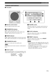
... up when this unit to the standby mode. Notes • If you set in the standby mode. Controls and functions ■Front panel GETTING STARTED 1 2 3 SUBWOOFER SYSTEM Soavo-900SW 1 2 3 1 2 3 STANDBY /ON PHASE B.A.S.S. Red: Lights up when you operate any button other than PRESET 1, 2, or 3, or when you turn on this unit next time...
... up when this unit to the standby mode. Notes • If you set in the standby mode. Controls and functions ■Front panel GETTING STARTED 1 2 3 SUBWOOFER SYSTEM Soavo-900SW 1 2 3 1 2 3 STANDBY /ON PHASE B.A.S.S. Red: Lights up when you operate any button other than PRESET 1, 2, or 3, or when you turn on this unit next time...

Owner's Manual
Page 10
... recommended, although you can obtain a good effect with one subwoofer. ( : subwoofer, : front speaker) ■When using one subwoofer Place the subwoofer on the outside of either the right or the left front speaker. ■When using two subwoofers Place the subwoofers on the outside of the subwoofer is not so critical because bass sound is placed directly...
... recommended, although you can obtain a good effect with one subwoofer. ( : subwoofer, : front speaker) ■When using one subwoofer Place the subwoofer on the outside of either the right or the left front speaker. ■When using two subwoofers Place the subwoofers on the outside of the subwoofer is not so critical because bass sound is placed directly...
Owner's Manual
Page 11
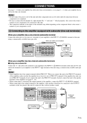
...terminals. Instead, connect this unit to the speaker terminals of the amplifier (see pages 9 - 11 when your amplifier has two-channel subwoofer terminals ■Using one set of PRE OUT terminals, do not connect this unit to the PRE OUT terminals. When you connect this... If connected, they will not produce sound. Notes • Some amplifiers have line output terminals labeled PRE OUT. CONNECTIONS See pages 7 - 8 when your amplifier has subwoofer (line out) terminal(s), or see pages 9 - 10). • When connecting to a monaural line output terminal of the amplifier, connect the INPUT 3 ( L ...
...terminals. Instead, connect this unit to the speaker terminals of the amplifier (see pages 9 - 11 when your amplifier has two-channel subwoofer terminals ■Using one set of PRE OUT terminals, do not connect this unit to the PRE OUT terminals. When you connect this... If connected, they will not produce sound. Notes • Some amplifiers have line output terminals labeled PRE OUT. CONNECTIONS See pages 7 - 8 when your amplifier has subwoofer (line out) terminal(s), or see pages 9 - 10). • When connecting to a monaural line output terminal of the amplifier, connect the INPUT 3 ( L ...

Owner's Manual
Page 12
... 2 R FROM AMPLIFIER L INPUT 1 L MONO L OUTPUT R TO SPEAKERS L R INPUT 3 R INPUT 2 R FROM AMPLIFIER L INPUT 1 Mono pin cable (not included) Subwoofer Subwoofer Amplifier ■Connecting to an amplifier equipped with a high cut function L MONO L If your amplifier to the INPUT 3 ( L /MONO) terminal of this unit using a commercially... available mono pin cable, and connect the "L" side subwoofer terminal of your amplifier can cut ) circuit. This brings you higher sound quality R because the signal routing in this...
... 2 R FROM AMPLIFIER L INPUT 1 L MONO L OUTPUT R TO SPEAKERS L R INPUT 3 R INPUT 2 R FROM AMPLIFIER L INPUT 1 Mono pin cable (not included) Subwoofer Subwoofer Amplifier ■Connecting to an amplifier equipped with a high cut function L MONO L If your amplifier to the INPUT 3 ( L /MONO) terminal of this unit using a commercially... available mono pin cable, and connect the "L" side subwoofer terminal of your amplifier can cut ) circuit. This brings you higher sound quality R because the signal routing in this...

Owner's Manual
Page 13
... to prevent short circuits. 3 Turn the knob counterclockwise to loosen. 4 Insert the bare wire into the hole. CONNECTIONS 2 Connecting to an amplifier not equipped with a subwoofer (line out) terminal Connect an amplifier (and front speakers) to this unit or the speakers, or both of them . • Make sure that the + and...
... to prevent short circuits. 3 Turn the knob counterclockwise to loosen. 4 Insert the bare wire into the hole. CONNECTIONS 2 Connecting to an amplifier not equipped with a subwoofer (line out) terminal Connect an amplifier (and front speakers) to this unit or the speakers, or both of them . • Make sure that the + and...

Owner's Manual
Page 14
... unit to the front speakers using a commercially available speaker cable. CONNECTIONS When your amplifier has one subwoofer Front speaker (R) Front speaker (L) L MONO L OUTPUT R TO SPEAKERS L R INPUT 3 R INPUT 2 R FROM AMPLIFIER L INPUT 1 Subwoofer Speaker terminals Amplifier ■Using two subwoofers Front speaker (R) LL MMOONNOO LL OOUUTTPPUUTT RR TTOO SSPPEEAAKKEERRSS LL RR IINNPPUUT T3 3 RR IINNPPUUTT2...
... unit to the front speakers using a commercially available speaker cable. CONNECTIONS When your amplifier has one subwoofer Front speaker (R) Front speaker (L) L MONO L OUTPUT R TO SPEAKERS L R INPUT 3 R INPUT 2 R FROM AMPLIFIER L INPUT 1 Subwoofer Speaker terminals Amplifier ■Using two subwoofers Front speaker (R) LL MMOONNOO LL OOUUTTPPUUTT RR TTOO SSPPEEAAKKEERRSS LL RR IINNPPUUT T3 3 RR IINNPPUUTT2...

Owner's Manual
Page 15
... that both terminals can output sound signals simultaneously • Connect one subwoofer Front speaker (R) L MONO L OUTPUT R TO SPEAKERS L Front speaker (L) Subwoofer R INPUT 3 R INPUT 2 R FROM AMPLIFIER L INPUT 1 Speaker terminals Amplifier ■Using two subwoofers L MONO L OUTPUT R TO SPEAKERS L R INPUT 3 R INPUT 2 R FROM AMPLIFIER L INPUT 1 Subwoofer (R) Subwoofer (L) L MONO L OUTPUT R TO SPEAKERS L R INPUT 3 R INPUT 2 R FROM AMPLIFIER L INPUT 1 Front speaker...
... that both terminals can output sound signals simultaneously • Connect one subwoofer Front speaker (R) L MONO L OUTPUT R TO SPEAKERS L Front speaker (L) Subwoofer R INPUT 3 R INPUT 2 R FROM AMPLIFIER L INPUT 1 Speaker terminals Amplifier ■Using two subwoofers L MONO L OUTPUT R TO SPEAKERS L R INPUT 3 R INPUT 2 R FROM AMPLIFIER L INPUT 1 Subwoofer (R) Subwoofer (L) L MONO L OUTPUT R TO SPEAKERS L R INPUT 3 R INPUT 2 R FROM AMPLIFIER L INPUT 1 Front speaker...

Owner's Manual
Page 18
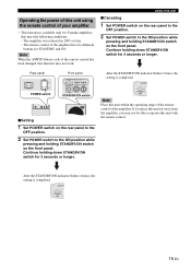
..., this unit automatically turns to 3 sets of the STANDBY/ON indicator changes to recall (1, 2 or 3). 14 En SUBW -900SW 31 2 3 PRESET STANDBY /ON Pressing SLEEP again cancels the sleep timer. 3 Press PRESET 1. USING THIS UNIT Storing the...PRESET 1 indicator lights up Even if you turn off this unit. PHASE MEMORY PRESET 1 2 3 1 2 HIGH CUT VOLUME 1 Front panel STANDBY/ON indicator SUBWOOFER SYSTEM Soavo-900SW 1 2 3 1 2 3 STANDBY /ON PHASE B.A.S.S. The current setting is cleared. Remote control 1 3 1 POWER STANDBY SLEEP B.A.S.S. Setting the sleep timer ...
..., this unit automatically turns to 3 sets of the STANDBY/ON indicator changes to recall (1, 2 or 3). 14 En SUBW -900SW 31 2 3 PRESET STANDBY /ON Pressing SLEEP again cancels the sleep timer. 3 Press PRESET 1. USING THIS UNIT Storing the...PRESET 1 indicator lights up Even if you turn off this unit. PHASE MEMORY PRESET 1 2 3 1 2 HIGH CUT VOLUME 1 Front panel STANDBY/ON indicator SUBWOOFER SYSTEM Soavo-900SW 1 2 3 1 2 3 STANDBY /ON PHASE B.A.S.S. The current setting is cleared. Remote control 1 3 1 POWER STANDBY SLEEP B.A.S.S. Setting the sleep timer ...
Owner's Manual
Page 19
...amplifier, you place this unit within the operating range of the remote control of the amplifier. Rear panel POWER ON OFF POWER switch Front panel SUBWOOFER SYSTEM Soavo-900SW 1 2 31 2 3 STANDBY /ON PHASE B.A.S.S. Continue holding STANDBY/ON switch on the front panel. SUBW STANDBY /ON 15 En After...on the rear panel to the OFF position. 2 Set POWER switch to the ON position while pressing and holding down STANDBY/ON switch for Yamaha amplifiers that meet the following conditions: - The amplifier was released in 2005 or later. - PRESET STANDBY /ON 0 40Hz 100Hz H-CUT ...
...amplifier, you place this unit within the operating range of the remote control of the amplifier. Rear panel POWER ON OFF POWER switch Front panel SUBWOOFER SYSTEM Soavo-900SW 1 2 31 2 3 STANDBY /ON PHASE B.A.S.S. Continue holding STANDBY/ON switch on the front panel. SUBW STANDBY /ON 15 En After...on the rear panel to the OFF position. 2 Set POWER switch to the ON position while pressing and holding down STANDBY/ON switch for Yamaha amplifiers that meet the following conditions: - The amplifier was released in 2005 or later. - PRESET STANDBY /ON 0 40Hz 100Hz H-CUT ...
Owner's Manual
Page 20
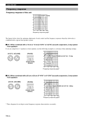
...subwoofer is combined with a typical front speaker system. ■EX.1 When combined with a 20 cm or 25 cm (7-14/16" or 9-13/16") acoustic suspension, 2 way system front speakers dB (H-CUT) (VOLUME) (PHASE) 90 0 40Hz 140Hz H-CUT 10 VOLUME OOFER SYSTEM S 1 PHASE reverse mode (Green) 80 70 60 Front speaker 50 Soavo-900SW...16 En dB (H-CUT) (VOLUME) 140Hz 0 40Hz H-CUT 10 VOLUME (PHASE) OOFER SYSTEM S 1 PHASE reverse mode (Green) 90 80 Soavo-900SW (H-CUT 60 - 70 Hz) 70 60 Front speaker 50 40 20 50 100 200 500Hz Frequency response graph* ■EX.2 When combined with...
...subwoofer is combined with a typical front speaker system. ■EX.1 When combined with a 20 cm or 25 cm (7-14/16" or 9-13/16") acoustic suspension, 2 way system front speakers dB (H-CUT) (VOLUME) (PHASE) 90 0 40Hz 140Hz H-CUT 10 VOLUME OOFER SYSTEM S 1 PHASE reverse mode (Green) 80 70 60 Front speaker 50 Soavo-900SW...16 En dB (H-CUT) (VOLUME) 140Hz 0 40Hz H-CUT 10 VOLUME (PHASE) OOFER SYSTEM S 1 PHASE reverse mode (Green) 90 80 Soavo-900SW (H-CUT 60 - 70 Hz) 70 60 Front speaker 50 40 20 50 100 200 500Hz Frequency response graph* ■EX.2 When combined with...
Owner's Manual
Page 22
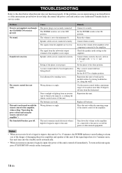
Speaker cables are weak. It is input, the power of your authorized Yamaha dealer or service center. The batteries are not connected correctly. Set the POWER switch to the other unused equipment. Raise the volume. Set the phase ... instructions given below when this unit is not turned on this unit or break up the parallel surface by standing waves. The signal from the subwoofer output terminal of fluorescent lamp etc. Direct sunlight or lighting from an inverter type of the amplifier is input to this unit for 5 minutes more...
Speaker cables are weak. It is input, the power of your authorized Yamaha dealer or service center. The batteries are not connected correctly. Set the POWER switch to the other unused equipment. Raise the volume. Set the phase ... instructions given below when this unit is not turned on this unit or break up the parallel surface by standing waves. The signal from the subwoofer output terminal of fluorescent lamp etc. Direct sunlight or lighting from an inverter type of the amplifier is input to this unit for 5 minutes more...


