
Owner's Manual
Page 2
... ribbon lead, change the lead-in all installation instructions. NOTE: This product has been tested and found in the users manual, may void your FCC authorization to coaxial type cable. If these requirements provides a reasonable level of assurance that is being affected by the interference. Cable/s supplied with this type of America or its subsidiaries. Utilize power outlets that interference...
... ribbon lead, change the lead-in all installation instructions. NOTE: This product has been tested and found in the users manual, may void your FCC authorization to coaxial type cable. If these requirements provides a reasonable level of assurance that is being affected by the interference. Cable/s supplied with this type of America or its subsidiaries. Utilize power outlets that interference...
Owner's Manual
Page 3
... cm free above the top panel and behind the rear panel. When the power supply unit is between 5˚C and 35˚C (41˚F and 95˚F). • Turn off all audio devices and speakers when connecting to clean the power supply unit. Remove the power cord from the AC outlet. Failure to do so is a fire and shock hazard. • Hold the power cord plug...
... cm free above the top panel and behind the rear panel. When the power supply unit is between 5˚C and 35˚C (41˚F and 95˚F). • Turn off all audio devices and speakers when connecting to clean the power supply unit. Remove the power cord from the AC outlet. Failure to do so is a fire and shock hazard. • Hold the power cord plug...
Owner's Manual
Page 4
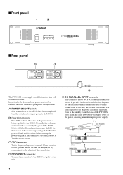
... blocked, since the ventilation path passes through them. As shown in a well ventilated location. sFront panel 1 2 POWER ON/ OFF OPERATION MONITOR +48V +12V +15V -15V NORMAL POWER SUPPLY sRear panel 5 DC PARALLEL INPUT CONNECT DISCONNECT 4 DC OUTPUT CONNECT PIN 2 +15V 4.2A PIN 5 -15V 4.2A PIN 6 +12V 4.1A PIN 9 +48V 0.2A DISCONNECT The PW3000M power supply should be installed in the following diagram, use the included parallel connection cable to make connections. Turn...
... blocked, since the ventilation path passes through them. As shown in a well ventilated location. sFront panel 1 2 POWER ON/ OFF OPERATION MONITOR +48V +12V +15V -15V NORMAL POWER SUPPLY sRear panel 5 DC PARALLEL INPUT CONNECT DISCONNECT 4 DC OUTPUT CONNECT PIN 2 +15V 4.2A PIN 5 -15V 4.2A PIN 6 +12V 4.1A PIN 9 +48V 0.2A DISCONNECT The PW3000M power supply should be installed in the following diagram, use the included parallel connection cable to make connections. Turn...
Owner's Manual
Page 5
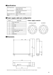
... W, 540 VA Europe: 380 W Others: 380 W 480mm x 103.5mm x 455mm 15kg sPower supply cable pin configuration Pin No. 1 2 3 4 5 6 7 8 9 10 Signal name Power supply remote +15 V ±15 V GND +48 V GND -15 V +12 V +12V GND/ power supply remote Power supply remote +48 V FRAME GND Power supply connector DC PARALLEL INPUT DC OUTPUT 321 7 6 54 10 9 8 123 4 5 67 8 9 10 sDimensions 292 405.6 D:455 56.8 49...
... W, 540 VA Europe: 380 W Others: 380 W 480mm x 103.5mm x 455mm 15kg sPower supply cable pin configuration Pin No. 1 2 3 4 5 6 7 8 9 10 Signal name Power supply remote +15 V ±15 V GND +48 V GND -15 V +12 V +12V GND/ power supply remote Power supply remote +48 V FRAME GND Power supply connector DC PARALLEL INPUT DC OUTPUT 321 7 6 54 10 9 8 123 4 5 67 8 9 10 sDimensions 292 405.6 D:455 56.8 49...


