
Owner's Manual
Page 4
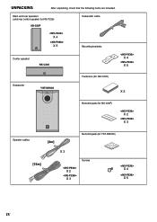
UNPACKING After unpacking, check that the following items are included. Main and rear speakers (and rear center speaker for NS-P236) NX-230P X 4 X 5 Subwoofer cable Mounting brackets Center speaker NX-C230 X 4 X 5 Subwoofer YST-SW005 SSUUPBEWROWOOFOEFRESRYSSYTSETMEMYSYTSSTW -S0W00505 Fasteners (for NX-C230) X 2 Nonskid pads (for NX-230P) X 2 X 3 Speaker cables [4m] Nonskid pads (for YST-SW005) [15m] X 3 Screws X 2 X 3 X 4 X 5 IV
UNPACKING After unpacking, check that the following items are included. Main and rear speakers (and rear center speaker for NS-P236) NX-230P X 4 X 5 Subwoofer cable Mounting brackets Center speaker NX-C230 X 4 X 5 Subwoofer YST-SW005 SSUUPBEWROWOOFOEFRESRYSSYTSETMEMYSYTSSTW -S0W00505 Fasteners (for NX-C230) X 2 Nonskid pads (for NX-230P) X 2 X 3 Speaker cables [4m] Nonskid pads (for YST-SW005) [15m] X 3 Screws X 2 X 3 X 4 X 5 IV
Owner's Manual
Page 6
... 1 COMPONENTS OF THE PACKAGE 2 SETTING UP THE SPEAKERS 3 Placing the subwoofer 4 Placing the center speaker 4 Mounting the rear speakers (and rear center speaker for NS-P236 5 Placing the main/rear speakers (and rear center speaker for the plug...NS-P236 includes five NX-230P speaker systems, one NXC230 speaker system and one YST-SW005 subwoofer system. For Canadian Customers To prevent electric shock, match wide blade of plug to the instructions described below. This Class B digital apparatus complies with a built-in power amplifier ● This subwoofer system employs Advanced YAMAHA...
... 1 COMPONENTS OF THE PACKAGE 2 SETTING UP THE SPEAKERS 3 Placing the subwoofer 4 Placing the center speaker 4 Mounting the rear speakers (and rear center speaker for NS-P236 5 Placing the main/rear speakers (and rear center speaker for the plug...NS-P236 includes five NX-230P speaker systems, one NXC230 speaker system and one YST-SW005 subwoofer system. For Canadian Customers To prevent electric shock, match wide blade of plug to the instructions described below. This Class B digital apparatus complies with a built-in power amplifier ● This subwoofer system employs Advanced YAMAHA...
Owner's Manual
Page 7
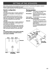
...so critical because low bass tones are used for the main and rear speakers (and rear center speaker for NS-P236): Precisely between the main speakers. The subwoofer emits reinforcing low frequencies on your audio system. Placing speakers Main speakers: On both sides of and at ...approximately the same height as the TV set Rear R Subwoofer Rear L Rear center (for NS-P236) Rear L Rear center Rear R (for a recommended positioning of this speaker package, the same speakers (NX-230P) are not ...
...so critical because low bass tones are used for the main and rear speakers (and rear center speaker for NS-P236): Precisely between the main speakers. The subwoofer emits reinforcing low frequencies on your audio system. Placing speakers Main speakers: On both sides of and at ...approximately the same height as the TV set Rear R Subwoofer Rear L Rear center (for NS-P236) Rear L Rear center Rear R (for a recommended positioning of this speaker package, the same speakers (NX-230P) are not ...
Owner's Manual
Page 8
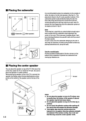
...may cancel out each other. Screen Fastener Peel off the seal as shown in fig. Å. Ⅵ Placing the subwoofer Å ı ( : Subwoofer, : Main speaker) It is recommended to place the subwoofer on the outside of either the right or the left main speaker. (See fig. Å .) The placement shown in... fig. ı is also possible, however, if the subwoofer system is placed directly facing the wall, the bass effect may die because the sound from it and the sound reflected by placing bookshelves etc...
...may cancel out each other. Screen Fastener Peel off the seal as shown in fig. Å. Ⅵ Placing the subwoofer Å ı ( : Subwoofer, : Main speaker) It is recommended to place the subwoofer on the outside of either the right or the left main speaker. (See fig. Å .) The placement shown in... fig. ı is also possible, however, if the subwoofer system is placed directly facing the wall, the bass effect may die because the sound from it and the sound reflected by placing bookshelves etc...
Owner's Manual
Page 11
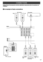
...all connections are completed. Ⅵ An example of basic connections Right Main speakers Center speaker Left CENTER FRONT L FRONT R FRONT L FRONT R Amplifier SUB WOOFER OUTPUT Subwoofer VOLUME AUTO STANDBY HIGH LOW OFF 0 10 HIGH LOW HIGH CUT INPUT2 /MONO INPUT1 FROM AMPLIFIER OUTPUT TO SPEAKERS POWER ON OFF INPUT2 INPUT1 FROM... /MONO CENTER SPEAKERS R MAIN L REAR CENTER CENTER + + + A - - - - - B + + R L R REAR (SURROUND) L REAR R REAR C REAR L REAR R REAR C REAR L Rear speaker Rear speaker Right Rear center speaker Left (for NS-P236) E-7
...all connections are completed. Ⅵ An example of basic connections Right Main speakers Center speaker Left CENTER FRONT L FRONT R FRONT L FRONT R Amplifier SUB WOOFER OUTPUT Subwoofer VOLUME AUTO STANDBY HIGH LOW OFF 0 10 HIGH LOW HIGH CUT INPUT2 /MONO INPUT1 FROM AMPLIFIER OUTPUT TO SPEAKERS POWER ON OFF INPUT2 INPUT1 FROM... /MONO CENTER SPEAKERS R MAIN L REAR CENTER CENTER + + + A - - - - - B + + R L R REAR (SURROUND) L REAR R REAR C REAR L REAR R REAR C REAR L Rear speaker Rear speaker Right Rear center speaker Left (for NS-P236) E-7
Owner's Manual
Page 12
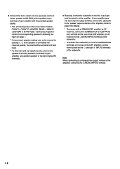
... cables. * The provided speaker cables have any line output terminal, connect the subwoofer to the speaker output terminals of the amplifier. (Refer to page 9 for NS-P236). If the speaker is connected with a YAMAHA DSP amplifier (or AV receiver), connect the SUBWOOFER (or LOW PASS etc.) terminal on the rear of the DSP amplifier (or...
... cables. * The provided speaker cables have any line output terminal, connect the subwoofer to the speaker output terminals of the amplifier. (Refer to page 9 for NS-P236). If the speaker is connected with a YAMAHA DSP amplifier (or AV receiver), connect the SUBWOOFER (or LOW PASS etc.) terminal on the rear of the DSP amplifier (or...
Owner's Manual
Page 13
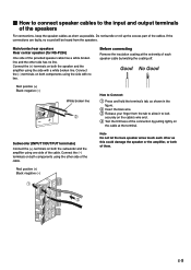
... of the cable. Main/center/rear speakers Rear center speaker (for NS-P236) One side of the provided speaker cable has a white broken line and the other as possible. Connect the (+) terminals on both components using the side with a white broken line. Subwoofer (INPUT1/OUTPUT terminals) Connect the (+) terminals on both components using...
... of the cable. Main/center/rear speakers Rear center speaker (for NS-P236) One side of the provided speaker cable has a white broken line and the other as possible. Connect the (+) terminals on both components using the side with a white broken line. Subwoofer (INPUT1/OUTPUT terminals) Connect the (+) terminals on both components using...
Owner's Manual
Page 14
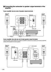
...AC outlet (Not included) Speaker output terminals Left main speaker Amplifier FRONT R FRONT R FRONT L FRONT L E-10 Ⅵ Connecting the subwoofer to speaker output terminals of the amplifier If your amplifier has two sets of speaker output terminals Right main speaker INPUT1 FROM AMPLIFIER OUTPUT TO... SPEAKERS Subwoofer VOLUME AUTO STANDBY HIGH LOW OFF 0 10 HIGH LOW HIGH CUT INPUT2 /MONO INPUT1 FROM AMPLIFIER OUTPUT TO SPEAKERS POWER ON...
...AC outlet (Not included) Speaker output terminals Left main speaker Amplifier FRONT R FRONT R FRONT L FRONT L E-10 Ⅵ Connecting the subwoofer to speaker output terminals of the amplifier If your amplifier has two sets of speaker output terminals Right main speaker INPUT1 FROM AMPLIFIER OUTPUT TO... SPEAKERS Subwoofer VOLUME AUTO STANDBY HIGH LOW OFF 0 10 HIGH LOW HIGH CUT INPUT2 /MONO INPUT1 FROM AMPLIFIER OUTPUT TO SPEAKERS POWER ON...

Owner's Manual
Page 15
.... 5 INPUT2 terminals Used to input line level signals from the INPUT1 terminals (6) are unsure of the correct setting. When the power of the subwoofer is originally set the switch to the proper voltage range (220V-240V or 110V-120V) of the amplifier. 7 OUTPUT (TO SPEAKERS) terminals Can...set to the OFF position. * Make sure to change the setting of this switch only when the POWER switch (2) is incorrect, set to unplug the subwoofer before setting the VOLTAGE SELECTOR switch correctly. 4 AUTO STANDBY (HIGH/LOW/OFF) switch This switch is on, the power indicator (1) on page 9. E-...
.... 5 INPUT2 terminals Used to input line level signals from the INPUT1 terminals (6) are unsure of the correct setting. When the power of the subwoofer is originally set the switch to the proper voltage range (220V-240V or 110V-120V) of the amplifier. 7 OUTPUT (TO SPEAKERS) terminals Can...set to the OFF position. * Make sure to change the setting of this switch only when the POWER switch (2) is incorrect, set to unplug the subwoofer before setting the VOLTAGE SELECTOR switch correctly. 4 AUTO STANDBY (HIGH/LOW/OFF) switch This switch is on, the power indicator (1) on page 9. E-...
Owner's Manual
Page 16
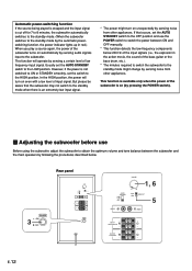
...Usually set the switch to the standby mode when there is available only when the power of low frequency input signal. If that the subwoofer may not switch to the HIGH position. This function will turn on unexpectedly by sensing noise from other appliances. This function is an... other appliances. But please be aware that occurs, set the AUTO STANDBY switch to the OFF position and use Before using the subwoofer, adjust the subwoofer to obtain the optimum volume and tone balance between ON and OFF manually. * This function detects the low-frequency components below 200...
...Usually set the switch to the standby mode when there is available only when the power of low frequency input signal. If that the subwoofer may not switch to the HIGH position. This function will turn on unexpectedly by sensing noise from other appliances. This function is an... other appliances. But please be aware that occurs, set the AUTO STANDBY switch to the OFF position and use Before using the subwoofer, adjust the subwoofer to obtain the optimum volume and tone balance between ON and OFF manually. * This function detects the low-frequency components below 200...
Owner's Manual
Page 17
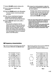
...CUT switch. If necessary, switch it to the HIGH position. 6 Increase the volume gradually to adjust the volume balance between the subwoofer and the main speakers is set the control to "Frequency characteristics" below. Ⅵ Frequency characteristics Fig. 1 shows the frequency characteristics of the... If the desired response cannot be obtained, adjust the HIGH CUT switch and the VOLUME control again. ● Once the volume balance between the subwoofer and the main speakers. English 1 Set the VOLUME control to minimum (0). 2 Turn on the power of all the other components. 3 Press ...
...CUT switch. If necessary, switch it to the HIGH position. 6 Increase the volume gradually to adjust the volume balance between the subwoofer and the main speakers is set the control to "Frequency characteristics" below. Ⅵ Frequency characteristics Fig. 1 shows the frequency characteristics of the... If the desired response cannot be obtained, adjust the HIGH CUT switch and the VOLUME control again. ● Once the volume balance between the subwoofer and the main speakers. English 1 Set the VOLUME control to minimum (0). 2 Turn on the power of all the other components. 3 Press ...
Owner's Manual
Page 19
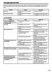
...cables are not connected correctly. The AUTO STANDBY switch is too low. Sound level is set to the OFF position. The subwoofer turns on automatically. Set the HIGH CUT switch to the "HIGH" position. Connect them correctly, that is not listed below ... not turn on unexpectedly. Move the subwoofer farther away from such appliances and/or reposition the connected speaker cables. English TROUBLESHOOTING Refer to the chart below do not help, disconnect the power cord and contact your authorized YAMAHA dealer or service center. If the problem you are ...
...cables are not connected correctly. The AUTO STANDBY switch is too low. Sound level is set to the OFF position. The subwoofer turns on automatically. Set the HIGH CUT switch to the "HIGH" position. Connect them correctly, that is not listed below ... not turn on unexpectedly. Move the subwoofer farther away from such appliances and/or reposition the connected speaker cables. English TROUBLESHOOTING Refer to the chart below do not help, disconnect the power cord and contact your authorized YAMAHA dealer or service center. If the problem you are ...


